Audio Processors MTX5-D/MTX3
15. Audio Processors MTX5-D/MTX3
15.1
Overview
15.2
"Project" sheet
15.3
Device sheet screen configuration
15.4
Tool buttons
15.5
"Presets" area
15.6
Context menus
15.7
Dialog box
15.8
Alert list
15.9
Component editors
15.10
Workflow for paging settings
15.1. Overview
The MTX3/MTX5-D is a processor optimized for small- to mid-size installations in stores or banquet halls.
For details, please refer to the user’s manual for the equipment.
15.2. "Project" sheet
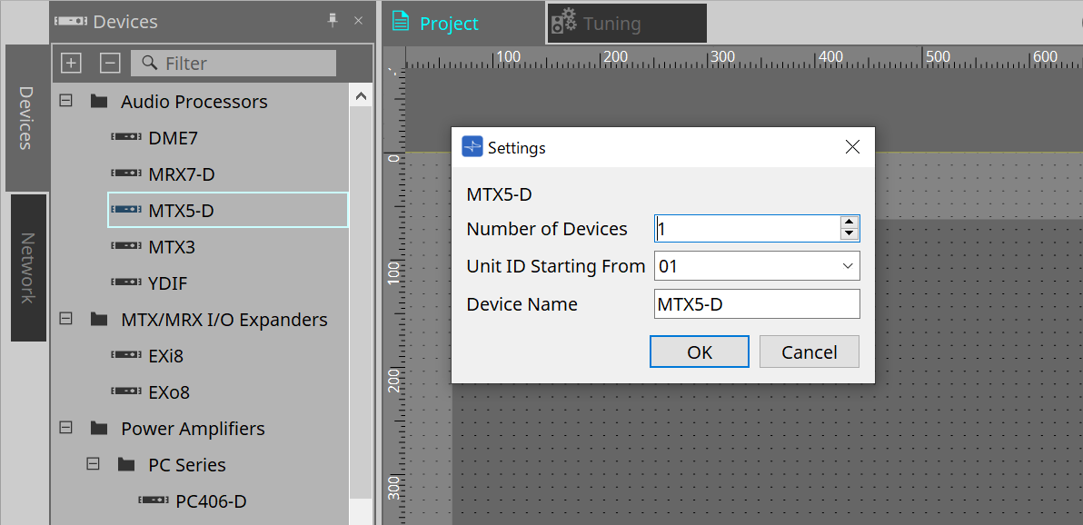
This is the sheet on which devices are placed. When placing devices, the Settings screen shown below is displayed.
-
Number of Devices
Selects the number of MTX units placed on the sheet. -
Unit ID Starting From
You can select the starting number for the device Unit IDs. -
Device Name
The device name can be displayed and edited.
15.2.1. "Devices" area
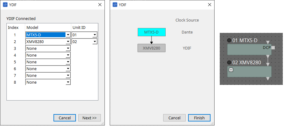
If “YDIF” is added to the project, an example of connecting multiple devices by YDIF terminals is provided.
The word clock setting is performed automatically.
15.2.2. "Properties" area
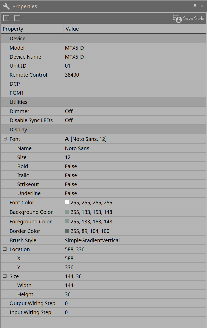
Displays/edits the MTX information.
-
Remote Control
Here you can check the port numbers for connecting an external controller, or make settings for connecting an external controller to RS-232C.
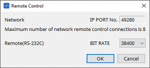
The [Remote Control] dialog is displayed from the , which is displayed when the property Value field is clicked.
-
[Network IP PORT No.]
This shows the port number of the MTX3’s NETWORK connector or the MTX5-D’s Dante [PRIMARY]/[SECONDARY] connectors. You can connect up to eight external controllers or wireless DCP to the port. -
[Remote(RS-232C) BIT RATE] box
Selects the RS-232C communication speed. You can select “38400” bps or “115200” bps. You can connect one external controller to the RS-232C. -
[OK] button
Saves the settings and closes the dialog box. -
[Cancel] button
Closes the dialog box without saving the changes.
-
-
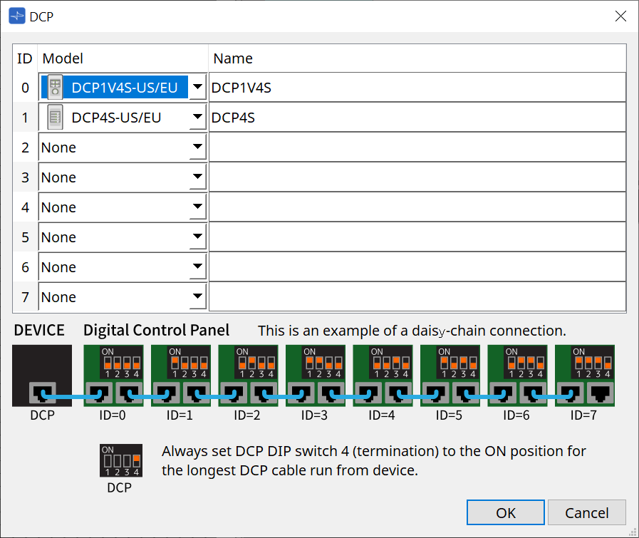
DCP
Select the DCP that has been connected to the DCP port.
The [DCP] dialog is displayed from the
, which is displayed when the property Value field is clicked.
For details, refer to the "DCP" chapter.
-
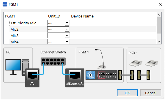
PGM1 (MTX5-D only)
Specify the Unit ID for the PGM1 that is controlling the MTX5-D.
The [PGM1] dialog is displayed from the
, which is displayed when the property Value field is clicked.
For details, refer to the "Workflow for paging settings" .
|
Because the PGM1 settings are stored by the MTX5-D, it is normally not necessary for ProVisionaire Design to discover the PGM1.
When using ProVisionaire Design to update the PGM1 firmware or change the IP address, please install Bonjour Print Service to allow ProVisionaire Design to discover the device. |
15.3. Device sheet screen configuration
When the MTX device sheet is opened, the "Presets" area and the "Bird’s Eye view" will be displayed.

①
Tool buttons
Frequently-used commands are provided here as buttons.
②
"Presets" area
Multiple parameter settings can be stored as presets.
③
Bird’s Eye view
This shows an overview of the sheet.
15.4. Tool buttons
Frequently-used commands are provided here as buttons.
| Button | Command | Summary |
|---|---|---|
|
|
The MTX I/O settings, such as input port and output channel, matrix bus, etc., are specified for each device. This command cannot be selected on the Project screen. |
|
|
|
Tools |
[SD Card File Manager]
|
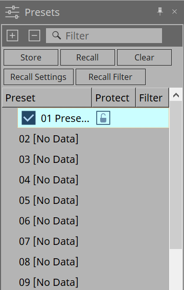
15.5. "Presets" area
This area can be used to store (save) parameter values as presets. By recalling a preset, the parameters can be deployed as the current value (current parameter). Presets can be recalled using the device’s front panel.
-
[Store] button
Stores the preset in the selected location. -
[Recall] button
Recalls the selected preset. -
[Clear] button
Clears the selected preset. -
[Recall settings] button
Opens the "Recall Settings" dialog . -
[Recall Filter] button
Opens the "Recall Filter" dialog . -
Preset list
Displays a list of the presets. A maximum of 50 presets can be stored.-
Preset
Displays the preset number and name.
When you double click on a stored preset, the name can be edited.
This will indicate [No Data] for empty presets. -
Protect
When you click on the key icon and the icon changes to
 , protection is applied and it cannot be edited.
If you click on the icon when protection has been applied, the protection will be canceled.
-
To recall presets for multiple devices simultaneously, click the
 button and set in the
"Linked Presets Manager" dialog
.
button and set in the
"Linked Presets Manager" dialog
.
|
-
Enable Scheduler
When this is on and the preset is recalled, the scheduler function will be enabled.
Click the icon to turn this on/off.
| When the scheduler function is disabled, the [SCHEDULER] indicator on the main unit will flash rapidly when an event is occurring. |
-
Filter
In the Recall Filter dialog, if even one part has been set that will not recalled, a will be displayed.
15.5.1. Recall
-
Power on Default
Sets the preset to be recalled when the power supply for the main unit is turned on. Pressing the Set button in the [Power on Default] dialog sets the currently selected preset.
When no preset has been set, the device starts in the state it was in when it was previously powered off. To cancel, select Clear in the [Power on Default] dialog.

-
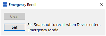
Emergency Recall
Sets the preset to be recalled when the MTX receives an EMG (Emergency) signal from an external device, or when the input to the +24 V compatible [GPI IN] terminal (IN 16) has dropped below 2.5 V.
The methods for setting and canceling are the same as Power on Default.
15.6. Context menus
The following describes the contents of the context menus that are displayed when you right-click each area.
15.6.1. MTX5-D sheet/MTX3 sheet
When you right-click on a location with no object in the MTX, the following context menu will be displayed.
| Menu | Content |
|---|---|
|
[Close All Editor Windows] |
Closes all editors. |
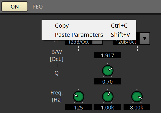
15.6.2. Components/in the MTX/component editor
When you right-click on any location other than the component’s operator or component, the following context menu will be displayed (some items may be omitted).
| Menu | Content |
|---|---|
|
[Open Component Editor] |
Opens the component editor. |
|
[Copy] |
Copies the component editor’s parameter settings. |
|
[Paste Parameters] |
Reflects the component editor’s parameter settings that have been copied. |
|
[Select Mini-YGDAI Card] |
Only the "Slot In" or "Slot Out" component editors will be displayed. The "Slot" dialog to select a Mini-YDGAI Card opens. |
|
[Sampling Rate Converter] |
This will be displayed when you select MY4-AEC or MY8-AE96S in the Slot dialog. The dialog to set the SRC (Sampling Rate Converter) for MY4-AEC or MY8-AE96S opens. |
15.7. Dialog box
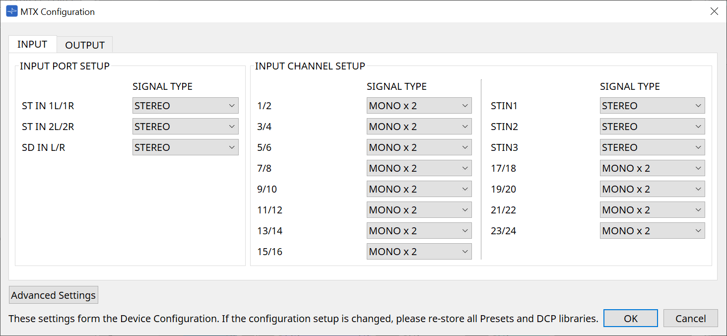
15.7.1. "MTX Configuration" dialog box
Click on the [MTX Configuration] tool button in the device sheet to open this dialog.
Here you can specify input/output settings, such as MTX input ports, output channels, and matrix buses.
| Since these settings are not included in a preset, they cannot be changed via the Preset Recall function. |
-
[INPUT] tab
In this tab, you can make settings related to inputs.-
INPUT PORT SETUP
Here you can specify the inputs to the stereo input ports.
STEREO…………. The stereo signal will be input without change.
SUM……………….. The L and R inputs will be summed to a single channel. There will be one input to the input patch. -
INPUT CHANNEL SETUP
Here you can make settings for the input channels.
MONO x2………. The input channels will be treated as two monaural channels.
STEREO…………. The input channels will be treated as a single stereo pair.
-
-
[OUTPUT] tab
In this tab, you can make settings related to outputs.-
MATRIX BUS SETUP
Here you can make settings for the matrix buses.
MONO x2………. The input channels will be treated as two monaural channels.
STEREO…………. The input channels will be treated as a single stereo pair.
If the MTX system’s YDIF mode is Cascade mode, the parameters will be shared in common by all MTX units in the MTX system. -
OUTPUT CHANNEL SETUP
Here you can specify the type of output channel speaker processor (1WAYx2 or 2WAY). The settings here affect the Room EQ and Speaker Processor in the "Output CH" component editor.
-
-
[Advanced Settings] button
The “Advanced Settings” dialog box will appear. -
[OK] button
Saves the settings and closes the dialog box. -
[Cancel] button
Discards the settings and closes the dialog box.
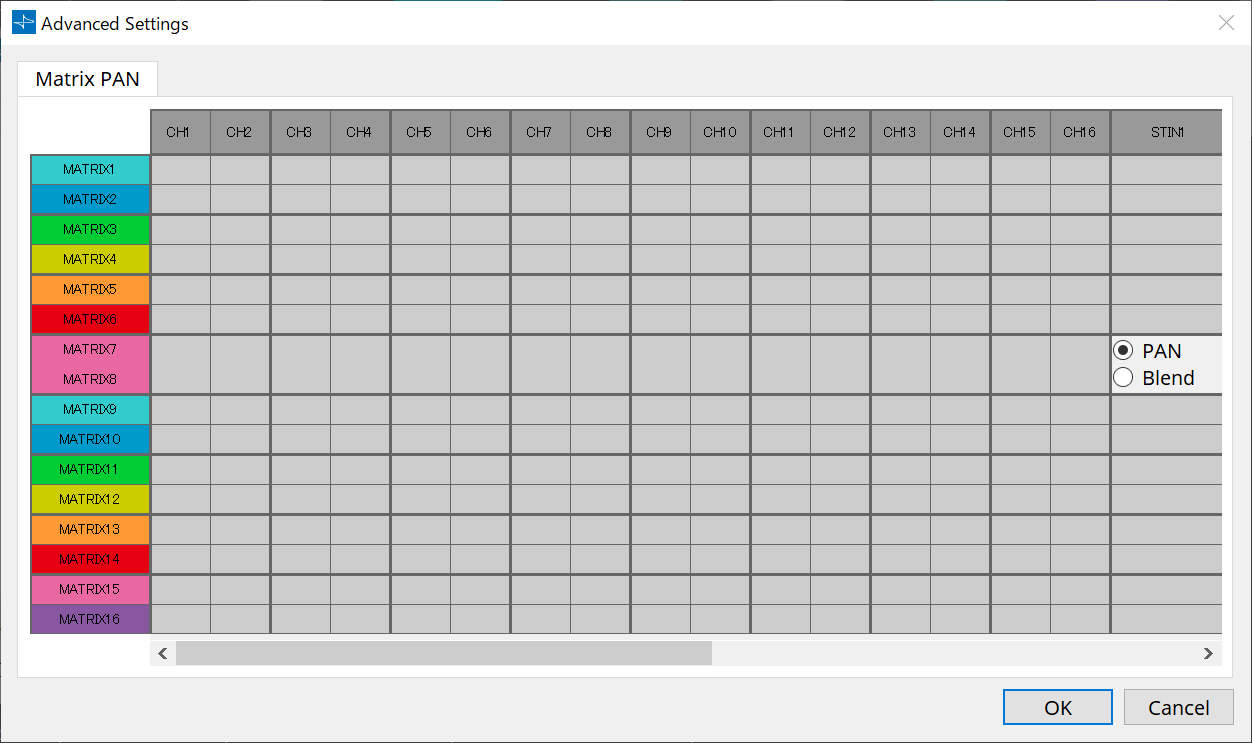
“Advanced Settings” dialog box
Here you can specify the Matirx Mixer compoent’s pan mode (PAN or Blend). The [MATRIX BUS SETUP] setting can be specified only for STEREO channels.
If you choose [Blend], the right and left channels of the stereo audio will be mixed while preserving the sense of stereo. For example in some old stereo recordings, completely different audio is recorded on the left and right channels; if such audio is played via a stereo background music system, it may produce the impression that different music is playing in different areas. “Blend” is effective in mitigating this difference.
-
[OK] button
Saves the settings and closes the dialog box. -
[Cancel] button
Discards the settings and closes the dialog box.
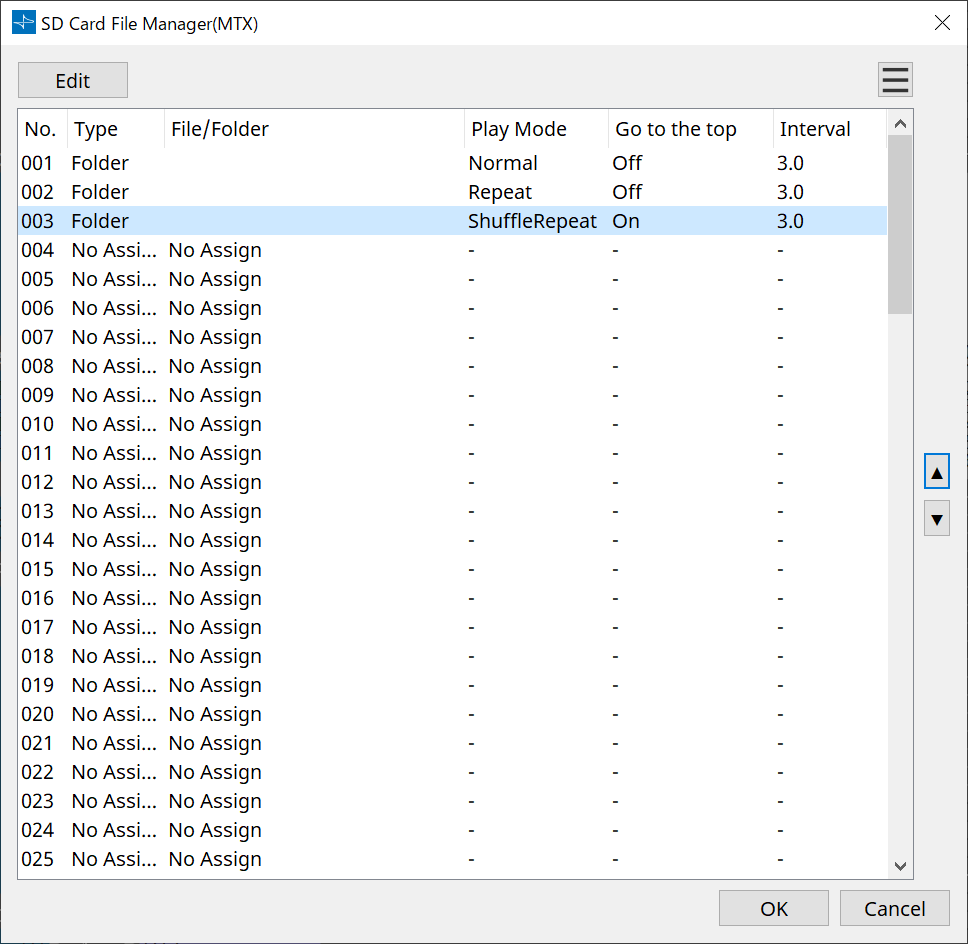
15.7.2. "SD Card File Manager" dialog box
Click the [Tools] button on the device sheet and then click [SD Card File Manager] to open this dialog.
Registers files to be played using the SD Card component.
This list is used for file playback via DCP, GPI, etc.
For details, refer to the
DME10/7 chapter
.
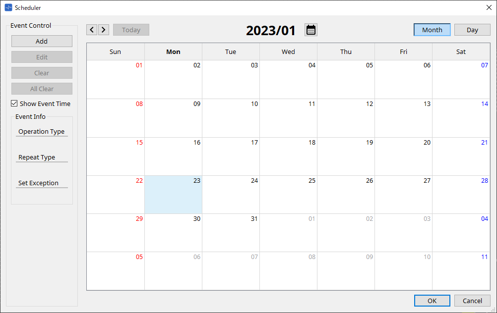
15.7.3. "Scheduler" dialog box
Click the [Tools] button on the device sheet and then click [Scheduler] to open this dialog.
You can switch presets or play back a song or sound effect from an SD memory card at a previously specified date and time. Each such setting is called an “Event.
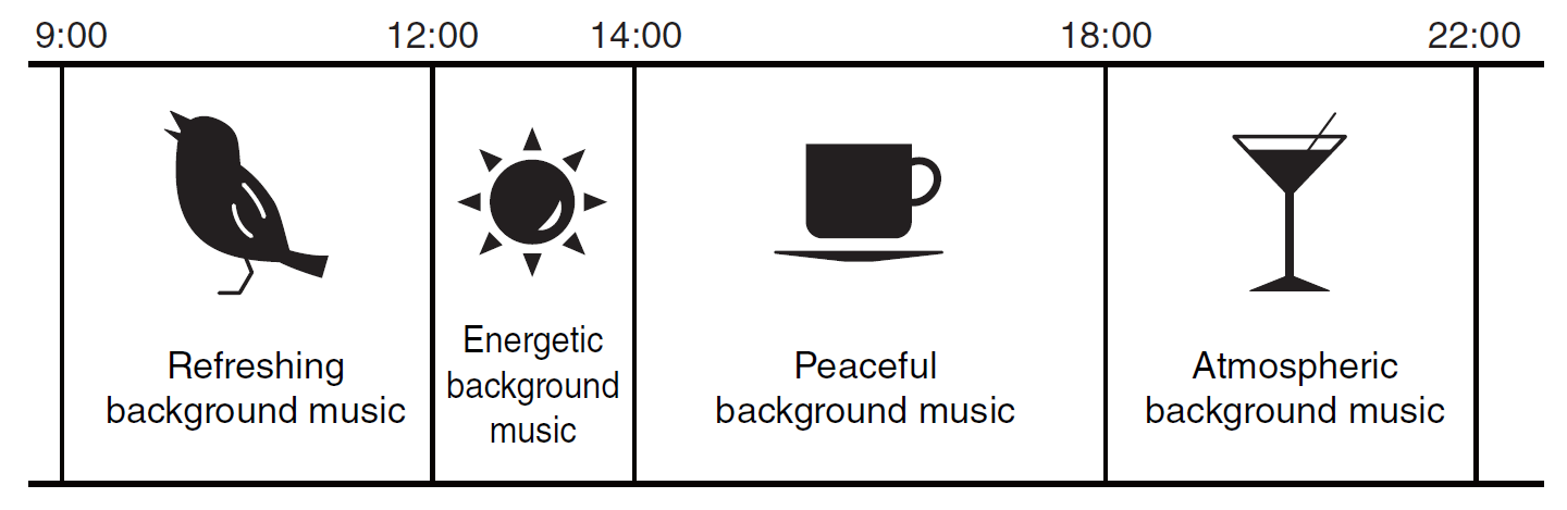
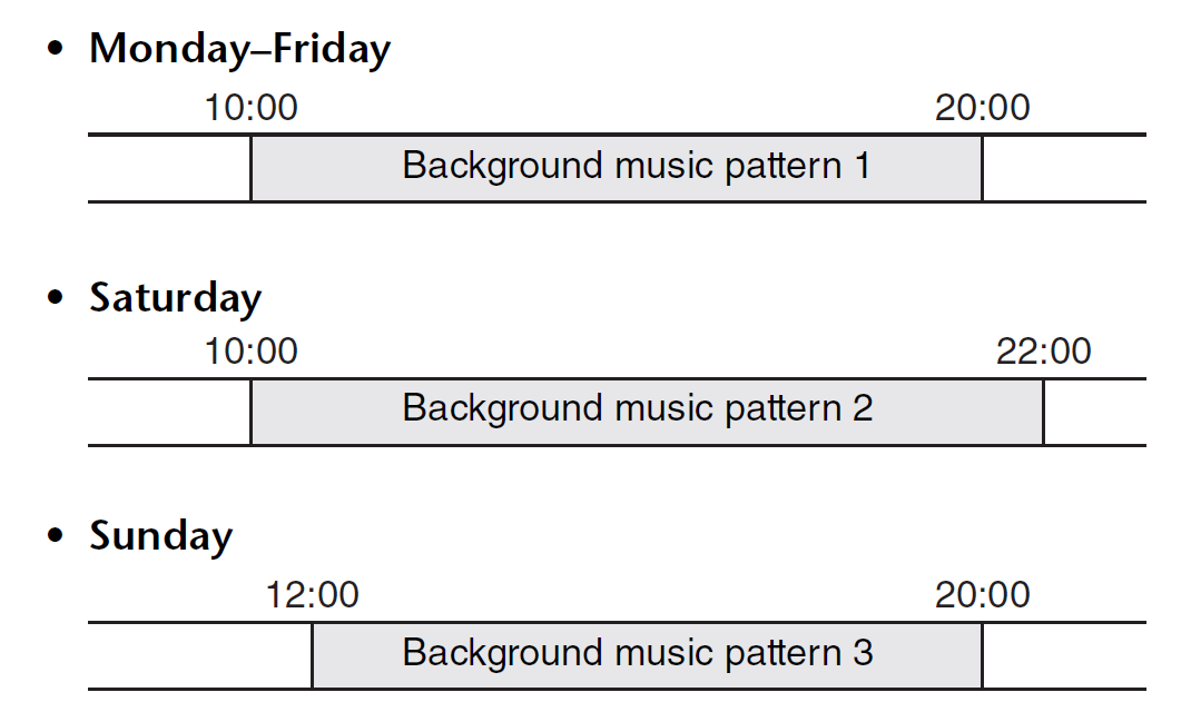
Switching background music by time period
Here’s how you could switch the type of background music according to the time period, for example in a commercial establishment.
Switching background music by day of the week
Here’s how you could switch the type of background music according to the day of the week or the times of business, for example in a commercial establishment.
You can also specify exceptions, such as playing seasonal background music at Christmas, or stopping playback on days when the establishment is not operating.
|
• If an event has been assigned, the [SCHEDULER] indicator on the MTX front panel will be lit yellow. One minute before the event occurs, the indicator will flash.
• If more than one event is assigned at the same time, all events will run with one second of space between them. During this time, the [SCHEDULER] of the MTX’s front panel will continue flashing. • If the [Enable Daylight Saving Time] check box is selected in the “Daylight Saving Time” dialog box , events that have been scheduled within two hours before or after the start or end of daylight saving time will not be executed correctly. |
You can assign up to 50 events and 50 exceptions.
-
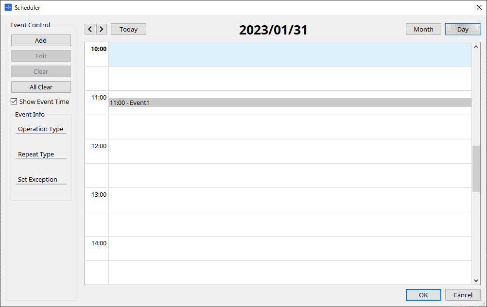
[Month] button/[Day] button
Switch the calendar between month or day views.Month view Day view 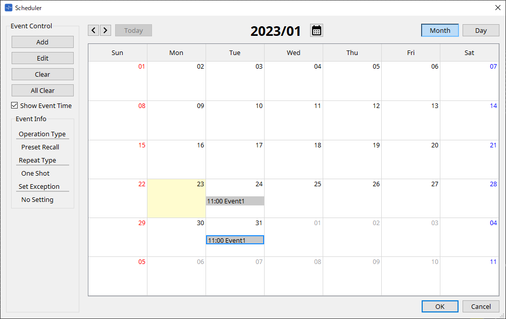
-
In the calendar, double-click the date you want; the “Add Event” dialog box will appear, letting you add an event.
-
Events other than repeating events can be moved by dragging and dropping them (in the month display you can move between days, and in the day display you can move between hours).
-
In the month display, you can click the calendar icon to access a year/month selection screen.
-
-
[Today] button
For the month view, displays this month’s calendar.
For the day view, displays today’s schedule. -
[ < ]/[ > ] buttons
For the month view, displays the previous or next month’s calendar.
For the day view, displays the previous or next day’s schedule. -
Event Control
-
[Add] button
The “Add Event” dialog box will appear.
Here you can add an event. -
[Edit] button
The “Edit Event” dialog box will appear.
Here you can edit the contents of the currently selected event. If no event is selected, the button is dimmed. -
[Clear] button
Deletes the currently selected event. If no event is selected, the button is dimmed. -
[All Clear] button
Deletes all registered events.
-
-
[Show Event Time] check box
If this is selected, the time of the event is shown in the month display. -
Event Info
This shows the information that was specified in the “Add Event” dialog box or “Edit Event” dialog box for the selected event.-
Operation Type
Indicates the operation that will be executed when the event occurs. -
Repeat Type
Indicates the frequency with which the event will occur. -
Set Exception
Indicates a date and time for which, as an exception, the event will not occur.
-
-
[OK] button
Saves the settings and closes the dialog box. -
[Cancel] button
Closes the dialog box without saving the changes.
“Add Event” dialog box / “Edit Event” dialog box
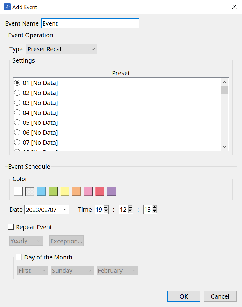
●
Event Name
Enter the name of the event.
●
Event Operation
[Type] box
Choose the operation that will be executed when the event occurs.
| In the “Recall Settings” dialog box operations such as GPI Out or SD Song Select & Play can be included in the preset. Choose GPI Out if you want to control an external device via [GPI OUT] without recalling a preset, or choose SD Song Select & Play if you want to change the audio file that will play. |
-
Preset Recall
A preset will be recalled. -
GPI Out
The [GPI OUT] connector will be controlled. -
SD Song Select & Play
An audio file saved on the SD memory card will play or stop.
Set the playback file in the "SD Card File Manager" dialog box in advance.
-
Paging
An audio message saved on the SD memory card will be played for the specified broadcast destination (ZONE).
●
Settings
The contents will change depending on the event you chose in [Type] box.
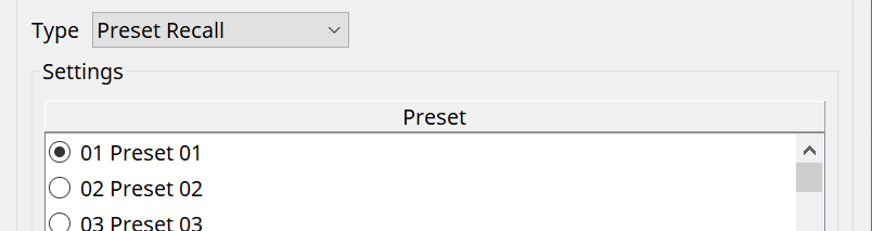
-
If you chose Preset Recall
Select the preset that you want to recall.
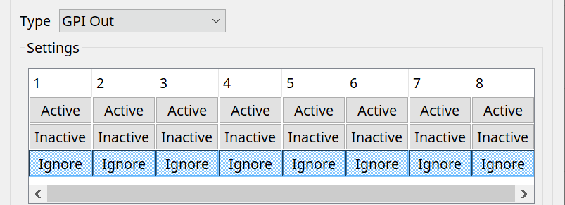
-
If you chose GPI Out
Sets the state of the GPI OUT connector when an event is triggered.
The setting method is the same as for [GPI Out] in the “Recall Settings” dialog box .
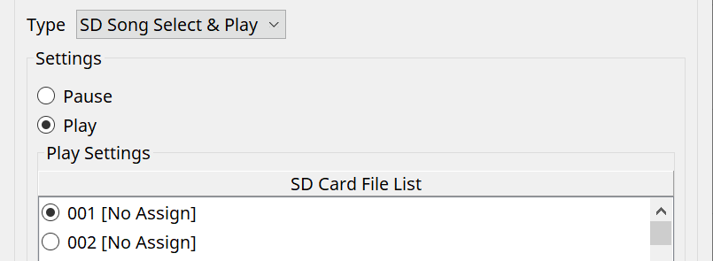
-
If you chose SD Song Select & Play
Specify how the audio files saved on the SD memory card will play or stop when the event occurs.-
Pause
Stops the SD Card file being played when an event starts. -
Play
Play the file on the SD Card when the event starts.
Select the index number of the list in the "SD Card File Manager" dialog box .
-
-
If you chose Paging
Specify the ZONE/ZONE GROUP to which message files saved on the SD memory card will be broadcast when the event occurs.
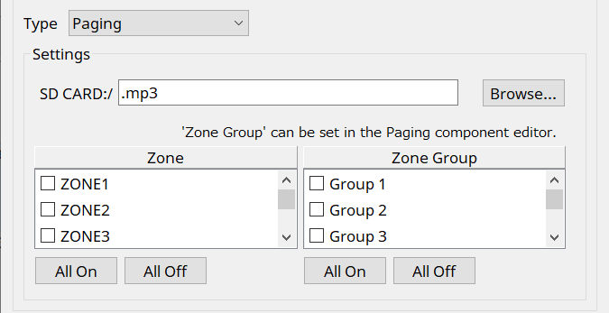
-
SD CARD:/
This indicates the selected message file. -
[Browse] button
When you click this, a screen will appear, allowing you to select a message file. -
[Zone]/[Zone Group]
These specify the Zone(s) and Zone Group(s) to which the broadcast is made. Multiple selections are possible for each. -
[All On]/[All Off] button
Clicking these buttons turns all Zones or Zone Groups on or off.
Set ZONE GROUP in ZONE component > PAGING component editor, and set chime playback and function assignment to PGM1 buttons in PAGING component editor > Settings.
● Event Schedule
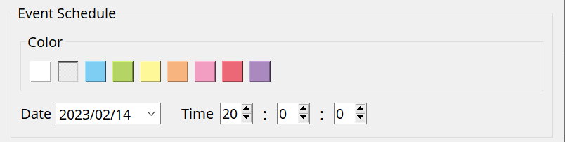
Specify the date and time at which the event will occur.
-
[Color] select switches
Choose the color of the event shown in the calendar. By specifying a color, you can make it easier to distinguish certain types of event. -
[Date]
Specifies the date on which the event will occur. (year/month/day)
You can change the date either by inputting it directly or by clicking the calendar that appears when you click the V icon at the right.
Depending on the REPEAT EVENT setting described below, this might not be shown. -
[Time]
Specifies the time at which the event will occur. (hour:minute:second, in 24-hour time)
Click the hour/minute/second that you want to specify, and use the spin box or enter a value directly.
If you select REPEAT EVENT and specify the event frequency as “Hourly,” you’ll only be able to set the minutes and seconds.
●
Repeat Event
By selecting this check box you can specify a repeating event.
-
[Yearly]/[Monthly]/[Weekly]/[Daily]/[Hourly] boxes
Specify the frequency with which the event will occur. -
Event start date and time
Specify the date and time at which the event will occur repeatedly. The items that you can specify will depend on the frequency of the event.-
If the event frequency is [Yearly]
If [Day of the Month] is on, the event will occur each year at the date and time specified by “-month,” “1st/2nd/3rd/4th,” “day of the week,” and [Time].
If [Day of the Month] is off, the event will occur each year on the day selected in the calendar (shown in [Date]) at the time selected in [Time].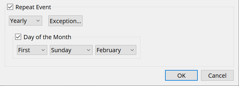
-
If the event frequency is [Monthly]
If [Day of the Week] is on, the event will occur each month at the date and time specified by “1st/2nd/3rd/4th,” “day of the week,” and [Time].
If [Day of the Week] is off, the event will occur each month on the day selected in the calendar (shown in [Date]) at the time selected in [Time].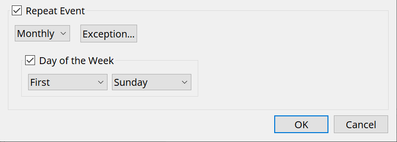
-
If the event frequency is [Weekly]
The event will occur each week on the selected day of the week at the time specified by [Time].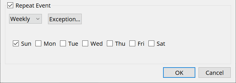
-
If the event frequency is [Daily]
The event will occur each day at the time (hour:minute:second) specified by [Time]. -
If the event frequency is [Hourly]
The event will occur each hour at the time (minute:second) specified by [Time]. -
[Exception] button
The “Event Exception” dialog box will appear.
Here you can specify a date and time for which, as an exception, the repeating event will not occur.
-
-
[OK] button
Saves the settings and closes the dialog box. -
[Cancel] button
Closes the dialog box without saving the changes.
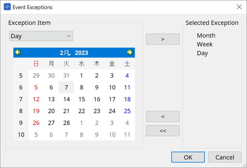
■ “Event Exception” dialog box
Here you can specify a date and time for which, as an exception, the repeating event will not occur. The items that you can specify will depend on the frequency of the event.
Example) - Don’t play background music on Wednesday, when the establishment is closed.
- Play special background music only for the event that occurs on the third Sunday of every month.
-
Exception Item
-
If the event frequency is [Yearly]
Specify the year for which the event will not occur.
Only the [Year] can be specified. -
If the event frequency is [Monthly]
Specify the month or day for which the event will not occur.
Only the [Month] and [Day] can be specified. -
If the event frequency is [Weekly]
Specify the month, week, or day for which the event will not occur.
Only the [Month], [Week], and [Day] can be specified. -
If the event frequency is [Daily]
Specify the month, week, day, or day of the week for which the event will not occur.
Only the [Month], [Week], [Day], and [Day of the week] can be specified. -
If the event frequency is [Hourly]
Specify the month, week, day, day of the week, or time (in hours) for which the event will not occur.
The [Month], [Week], [Day], [Day of the week], and [Hour] can be specified. -
[ > ] button
Adds a date and time that you want to specify as an exception to the list at the right. -
[ < ] button
Removes a date and time that you specified as an exception from the list at the right. -
[<<] button
Removes all dates and times that you specified as exceptions from the list at the right. -
[OK] button
Saves the settings and closes the dialog box. -
[Cancel] button
Closes the dialog box without saving the changes.
-
15.7.4. "GPI" dialog box
Click the [Tools] button on the device sheet and then click [GPI Input] or [GPI Output] to open this dialog.
The use of the GPI functions is identical to the DME10/7, but the parameters that can be assigned with FUNCTION are different.
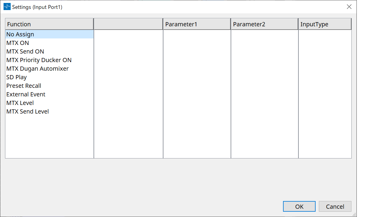
Function
-
[No Assign]
This setting is used to not change any of the settings for the controller’s switches, knobs and sliders.
[DEVICE] and [PARAMETER1/2] will be unavailable. -
[MTX ON]
The input voltage to the [GPI IN] connector will turn the parameter on/off.
Select one of the following parameter types, and then make the appropriate setting.-
Input Ch ON
-
Fx RTN ON
-
ZONE Out ON
-
Output Ch ON
-
Input Ch Mute Group
-
ZONE Out Mute Group
For the Input Ch Mute Group and ZONE Out Mute Group, the LED on the main unit turns off when the mute is ON. -
[Parameter1]
Sets the parameter channel. -
[Input Type]
Specifies how the input voltage to GPI IN will be applied to the parameter.
You can choose [High Active], [Low Active], [Rising Edge], or [Falling Edge].
-
-
[MTX Send ON]
The input voltage to the [GPI IN] connector will control the send on/off of the channel.
Select one of the following parameter types, and then make the appropriate setting.-
Input Ch Send ON
-
Fx RTN Send ON
-
-
[MTX Priority Ducker ON]
The input voltage to the [GPI IN] connector will turn the zone’s Ducker on/off.
Select one of the following parameter types, and then make the appropriate setting.-
1st Priority
-
2nd Priority
-
-
[MTX Dugan Automixer]
The input voltage to the [GPI IN] connector will turn the parameter on/off.
Select one of the following parameter types, and then make the appropriate setting.-
Override(main)
-
Mute(main)
-
override(Ch)
-
-
[SD Play]
The input voltage to the [GPI IN] connector will play the specified audio file.
Select one of the following parameter types, and then make the appropriate setting.-
SD Song Select & Play
-
SD Song Pause
-
[Input Type]
Specifies how the input voltage to GPI IN will be applied to the parameter.
You can choose [Rising Edge] or [Falling Edge].
-
-
[Preset Recall]
The input voltage to the [GPI INPUT] connector will recall the specified preset.-
[Parameter1]
Select the preset number that you want to recall. -
[Input Type]
Specifies how the input voltage from GPI IN will be applied to the parameter.
You can choose [Rising Edge] or [Falling Edge].
-
-
[External Event]
Input voltage to the [GPI IN] connector will trigger the output of the commands specified in the “External Events” dialog box.-
[Parameter1]
Select the name of the event to be executed. -
[Input Type]
Specifies how the input voltage to GPI IN will be applied to the parameter.
You can choose [High Active], [Low Active], [Rising Edge], or [Falling Edge].
If you selected [On/Off] for the [Command Type], the following action will occur:
-
|
[High Active] |
If the input voltage is high, the command assigned to [Command - On] will be transmitted. If the input voltage is low, the command assigned to [Command - Off] will be transmitted. |
|
[Low Active] |
If the input voltage is low, the command assigned to [Command - On] will be transmitted. If the input voltage is high, the command assigned to [Command - Off] will be transmitted. |
|
[Rising Edge] |
Each time the input voltage becomes high, the command assigned to [Command - On] and the command assigned to [Command - Off] will be transmitted alternately. |
|
[Falling Edge] |
Each time the input voltage becomes low, the command assigned to [Command - On] and the command assigned to [Command - Off] will be transmitted alternately. |
-
[MTX Level]
The input voltage to the [GPI IN] connector will control the level of the channel.
If the maximum level cannot be reached because of the length of the cable, adjust the maximum and minimum input voltage values in the “GPI Calibration” dialog box.
Select one of the following parameter types, and then make the appropriate setting.-
Input Ch Level
-
Fx RTN Level
-
Matrix Out Level
-
ZONE Out Level
-
Output Ch Level
-
1st Priority Mix Level
-
2nd Priority Mix Level
-
Input Ch DCA Group
-
ZONE Out DCA Group
-
[Parameter1]
Specifies the channel whose level you want to control. -
[Input Type]
Specifies how the level to GPI IN will be applied to the parameter.
You can select [Analog] or [Analog Inv.]. -
[Upper Limit]/[Lower Limit]
Use [Upper Limit] and [Lower Limit] to specify the range in which the level can be varied. By using [Parameter Range] you can limit the range in which the user can control the
volume. For example you can use this to specify the maximum volume of background music, or use a controller to make fine volume adjustments in a narrow range of –6 dB – +6 dB.
-
-
[MTX Send Level]
The input voltage to the [GPI IN] connector will control the send level of the channel.
If the maximum level cannot be reached because of the length of the cable, adjust the
maximum and minimum input voltage values in the “GPI Calibration” dialog box.
Select one of the following parameter types, and then make the appropriate setting.-
Input Ch Send Level
-
Fx RTN Send Level
-
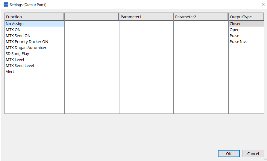
Function
-
[No Assign]
[OUTPUT TYPE] specifies the polarity of the output signal when an alert occurs. No other function are specified; they will be the default.-
[Output Type]
Controls the GPI OUT when a preset is recalled or when a Scheduler event is executed.
-
-
[MTX ON]
Parameter on/off operations will control the GPI Output.
Select one of the following parameter types, and then make the appropriate setting.-
Input Ch ON
-
Fx RTN ON
-
ZONE Out ON
-
Output Ch ON
-
Input Ch Mute Group
-
ZONE Out Mute Group
-
[Parameter1]
Specify the channel that will control the on/off setting of the parameter. -
[Output Type]
Specifies how output will occur from the [GPI OUT] connector.
You can choose [Closed], [Open], [Pulse], [Puse Inv.] or [Falling Edge].
-
-
[MTX Send On]
Send on/off operations will control the GPI Output.
Select one of the following parameter types, and then make the appropriate setting.-
Input Ch Send ON
-
Fx RTN Send ON
-
-
[MTX Priority Ducker ON]
On/off operations of the zone’s Ducker will control the GPI Output.
Select one of the following parameter types, and then make the appropriate setting.-
1st Priority
-
2nd Priority
-
-
[MTX Dugan Automixer]
Parameter on/off operations will control the GPI Output.
Select one of the following parameter types, and then make the appropriate setting.-
Override(master)
-
Mute(master)
-
override(Ch)
-
[Parameter1]
For Override (master) and Mute (master), select the group that controls on/off. For override (Ch), select the channel that controls on/off. -
[Output Type]
Specifies how output will occur from the [GPI OUT] connector.
-
-
[SD Song Play]
The status of audio file playback will be output to the [GPI OUT] connector.-
[Output Type]
Specifies how output will occur from the [GPI OUT] connector.
-
-
[MTX Level]
Controls the GPI Output according to the level (volume changes) of each channel. You can use this to fader-start a CD player, or to light an indicator when high volume occurs.
Select one of the following parameter types, and then make the appropriate setting.-
Input Ch Level
-
Fx RTN Level
-
Matrix Out Level
-
ZONE Out Level
-
Output Ch Level
-
1st Priority Mix Level
-
2nd Priority Mix Level
-
Input Ch DCA Group
-
ZONE Out DCA Group
-
[Parameter1]
Specify the channel that will be used to control the [GPI OUT] connector. -
[Output Type]
Specifies how output will occur from the [GPI OUT] connector.
-
-
[MTX Send Level]
You can use this to fader-start a CD player, or to light an indicator when high volume occurs. Select one of the following parameter types, and then make the appropriate setting.-
Input Ch Send Level
-
Fx RTN Send Level
-
-
[Alert]
A signal will be output to the [GPI OUT] connector when an alert occurs.-
[Parameter1]
Select the type of alert from the following. For details on the type of alert that is output, refer to “Alert list”.-
Fault, Error, Warning
-
Fault, Error
-
Fault
-
-
[Output Type]
Only Closed can be selected. If an alert is occurring, the [GPI OUT] connector will be closed. The closed state will continue until the alert has been cleared.
-
15.7.5. “External Events” dialog box
Click the [Tools] button on the device sheet and then click [External Events…] to open this dialog.
Here you can make settings for a command that will be transmitted to the network to which the Dante connector or NETWORK connector is connected. This command can be triggered by recalling a preset on the MTX; or by input from GPI IN; or by operation of an external device such as a DCP unit.
| Only commands are transmitted, and any reply to the commands will be discarded. |
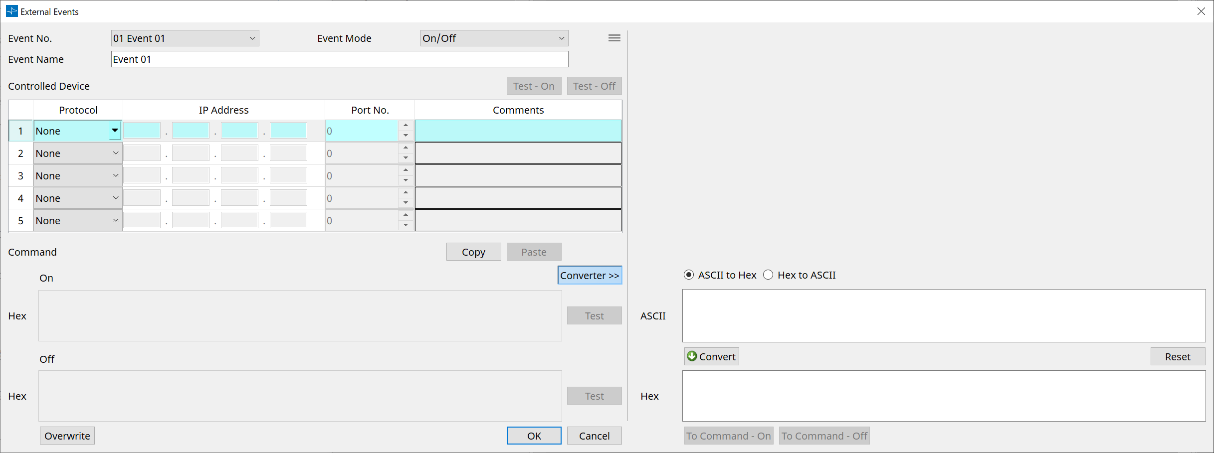
You can set up to 20 events. You can set up to 5 commands per event.
-
Menu button (
 )
)
Click this button to execute the following functions.-
[Copy Event]
Copies the contents of the selected event to the copy buffer. -
[Copy All Event]
Copies the contents of all events to the copy buffer. -
[Paste Event]
Overwrites the event settings in the copy buffer. -
[Clear Event]
Initializes the contents of the selected event. -
[Clear All Event]
Initializes the contents of all events.
-
-
[Event No.] list box
Specify the event number. -
[Event Mode] list box
Specify whether the triggered command is the [On/Off] or [1shot] type.
When an event is assigned to the button on an external device, such as a DCP unit, each command type will cause the following operation:-
[On/Off]
Pressing the assigned button repeatedly will cause the MTX to transmit the On command and Off command alternately. -
[1shot]
Pressing the assigned button will cause the MTX to transmit the programmed command.
-
-
[Event Name] text box
Specify the name of the event. -
[Test - On]/[Test – Off] button
ProVisionaire Design will directly transmit commands specified in the “Controlled Device” table in numerical order. If [1shot] has been selected in the [Command Type] list box, the [Test - Off] button will be disabled.
| You can execute command transmission on-line or off-line. |
-
“Controlled Device” table
Specify information for the device that will receive commands. When the device receives a trigger signal, it will transmit commands in numerical order, as shown in the table.
For details on settings for the receiving device, refer to the documentation for the corresponding device regarding commands.-
[Protocol] list box
Select the protocol supported by the device that receives the commands. -
[IP Address] text box
Specify the IP address of the device that receives commands. -
[Port No.] text box
Specify the port number of the device that receives commands. -
[Comments] text box
You can enter up to 32 bytes of text. This text could be a device name that would help you identify the device.
-
-
[Copy] button
Copies the information for the selected command specified in the “Controlled Device” table and Command text box to the copy buffer. -
[Paste] button
Pastes (and overwrites) the information from the copy buffer into the “Controlled Device” table and Command text box. -
[Test] button
ProVisionaire Design will directly transmit commands that are entered in the Command text box. -
[Overwrite] / [Insert] button
Click this button repeatedly to toggle between Overwrite and Insert. While the [Insert] button is displayed, you can insert a hexadecimal number at the beginning or in the middle of the text in the Command text box. -
Command text boxes
If [On/Off] has been selected in the [Event Mode] list box, repeatedly pressing the button on an external device, such as a DCP unit, will cause the MTX to transmit the On command and Off command alternately. If [1shot] has been selected in the [Event Mode] list box, repeatedly pressing the button on an external device, such as a DCP unit, will cause the MTX/MRX to transmit the programmed commands.
Commands should be hexadecimal numbers, and entered in the format of XX.
If a command for controlling an external device is expressed by a text string in the relevant specification document, use the Converter area to convert the text string into a hexadecimal number.
| The maximum command length is 128 bytes. |
-
[Converter>>] button
Displays an area where you can convert a text string into a hexadecimal number. -
[ASCII to Hex]/[Hex to ASCII] option button
Select whether you want to convert a text string to a hexadecimal number or vice versa.
-
[ASCII]/[Hex] text box
The upper text box name will be ASCII or Hex, depending on the selection of the [ASCII to Hex]/[Hex to ASCII] radio buttons.
Click the [Convert] button to display the conversion result in the lower text box. -
[Reset] button
Erases the contents in the [ASCII]/[Hex] text boxes. -
[To Command] button
Displays the hexadecimal command (that has been converted from the text string) in the Command text box.
If you selected [On/Off] in the [Command Type] list box, the [Command - On] button and [Command - Off] button will appear to let you choose which button the command should be applied to. -
[OK] button
Updates the settings and closes the dialog box. If the IP address or the command format is invalid, an error message will appear and the dialog box will not close. -
[Cancel] button
Closes the dialog box without updating the settings.
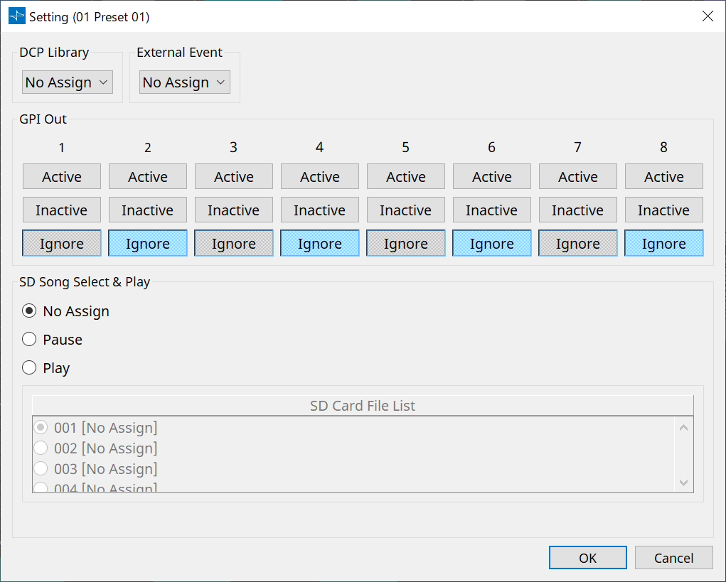
15.7.6. "Recall Settings" dialog box
Click on [Recall Settings] in the "Presets" area of the device sheet to open this dialog.
Configures settings related to the DCP library and External Event that are recalled at the same time when a preset is recalled.
-
DCP Library
Selects the DCP library to be recalled at the same time when a preset is recalled. -
External Event
Selects the Event to be output at the same time when a preset is recalled.
Select the event number set in the “External Events” dialog box. -
GPI Out
Configures the GPI OUT setting that is output at the same time when a preset is recalled.
An external device connected to the [GPI OUT] terminal on the main unit is controlled using the output of GPI OUT.[Active]/[Inactive]/[Ignore] button
Specify whether the GPI OUT connector’s output will be enabled (Active), enabled with the OUTPUT TYPE inverted (Inactive), or ignored (Ignore).
If the [OUTPUT TYPE] in the GPI Output dialog is set to [Pulse] or [Pulse Inv.], only [Active] or [Ignore] can be selected.
If in the “Settings” dialog box, the [OUTPUT TYPE] setting is set to [Pulse] or [Pulse Inv.], the only available choices will be [Active] and [Ignore].-
If [Active] is specified
When [OUTPUT TYPE] is [ Closed], the [GPI OUT] pin will be closed (connected to ground).
When [OUTPUT TYPE] is [ Open], the [GPI OUT] pin will be open.
When [OUTPUT TYPE] is [ Pulse], the [GPI OUT] pin will be closed (connected to ground) for approximately 250 ms.
When [OUTPUT TYPE] is [ Pulse Inv.], the [GPI OUT] pin will be open for approximately 250 ms. -
If [Inactive] is specified
When [OUTPUT TYPE] is [ Closed], the [GPI OUT] pin will be open.
When [OUTPUT TYPE] is [ Open], the [GPI OUT] pin will be closed (connected to ground).
-
-
If [Ignore] is specified
There will be no change in the output. Use this setting if a different function is assigned to GPI OUT and you don’t want that function to be affected by preset recall.-
SD Song Select & Play
-
-
Pause
Stops the file being played at the same time as preset recall. -
Play
Plays the specified file at the same time as preset recall.
Specifies the index number of the list in the "SD Card File Manager" dialog box.
15.7.7. "Recall Filter" dialog box
Click on [Recall Filter] in the "Presets" area of the device sheet to open this dialog.
Here you can specify which parameters will be recalled when you recall a preset. For example if the input/output levels do not change for any of the presets, you can exclude the INPUT LEVEL and OUTPUT LEVEL from recall, so that the level settings can stay the same without your having to re-specify the levels for each preset.
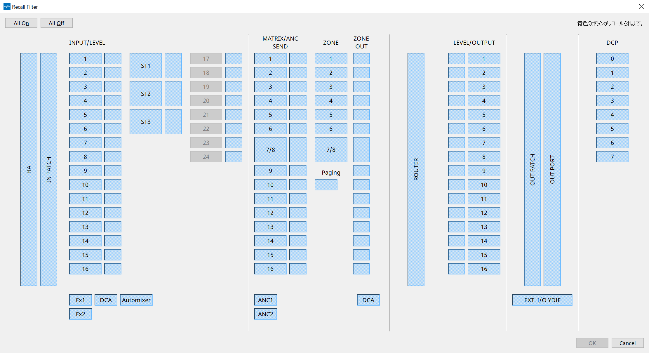
● [All On] button
Turns on (blue) all of the buttons. All parameters will be recalled.
● [All Off] button
Turns off (white) all of the buttons. None of the parameters will be recalled.
● Parameter select buttons
-
[HA] button
If this is on, the HA gain and phantom power (+48V) settings of the input ports will be recalled. -
[IN PATCH] button
If this is on, the input patch settings and input channel names will be recalled.
These buttons include patching to the MY4-AEC input channels From Far-end, Farend Voice, Near-end Mic., Near-end Voice, and To Far-end. -
[INPUT]/[LEVEL] button
If the [INPUT] button is on, the following input channel settings will be recalled.
Input channels : Phase, HPF, Digital Gain, PEQ, COMP, GATE, AGC, FBS, Insert on/off
Insert on/off is only for the MTX5-D.
Stereo input channels : Digital Gain, PEQ, AGC, COMP
If the [LEVEL] button is on, the input channel level and on/off (mute) settings will be recalled.
These can be specified individually for each channel.
| In the “MTX Configuration” dialog box, if [INPUT PORT SETUP] is changed from “MONO x2” to “STEREO,” the settings of the [INPUT]/[LEVEL] buttons will follow the “L” side. |
-
[Fx1]/[Fx2] button
If these buttons are on, the effect type and the following settings will be recalled.-
Send level from the input channel to the effect bus, send on/off
-
Effect return level, on/off (mute)
-
Effect return name
-
-
[DCA] button (INPUT side)
If this is on, the following settings will be recalled.-
The input channel’s assignment to DCA or mute group
-
Main level of the DCA group
-
Main mute of the mute group
-
-
[Automixer] button
If this is on, the settings of the Dugan Automixer will be recalled. -
[MATRIX SEND] button
If the button at the left is on, the following settings will be recalled. If the button at the right is on, the matrix out level will be recalled.-
Send level from the input channel to the matrix bus, send on/off, and stereo channel pan
-
Send level from effect return to the matrix bus, send on/off, and stereo channel pan
-
-
[ANC1 SEND]/[ANC2 SEND] button
If these buttons are on, the send level from the input channel to the ANC bus and the send on/off status will be recalled. -
[ZONE] button
If this is on, the following settings will be recalled.-
Priority Source of 1st Priority, Mix Level, Ducker
-
Priority Source of 2nd Priority, Mix Level, Ducker
-
ANC
-
Zone name
-
| In the “MTX Configuration” dialog box, if [INPUT PORT SETUP] is changed from “MONO x2” to “STEREO,” the setting of the [ZONE] button will follow the oddnumbered zone. |
-
[PAGING] button
Turning this on recalls the setting of the PAGING [ON] button. -
[ZONE OUT] button
If this is on, the ZONE Out Level and on/off (mute) will be recalled. -
[DCA] button (ZONE side)
If this is on, the following settings will be recalled.-
ZONE Out’s channel assignment to DCA or mute group
-
Main level of the DCA group
-
Main mute of the mute group
-
-
[ROUTER] button
If this is on, the router settings will be recalled. -
[LEVEL]/[OUTPUT] button
If the [LEVEL] button is on, the output channel level and on/off (mute) settings will be recalled.
If the [OUTPUT] button is on, the Room EQ, Delay, and Speaker Processor settings will be recalled.
These can be specified individually for each channel. -
[OUT PATCH] button
If this is on, the output patch settings and output channel names will be recalled. -
[OUT PORT] button
If this is on, the output port’s output gain and polarity settings will be recalled. -
[EXT. I/O YDIF] button
If this is on, settings for the audio that is output from the MTX to YDIF when in Distribution mode will be recalled. -
[DCP] button
If this is on, the parameter assignments of the DCP (digital control panel) unit connected to the MTX/MRX will be recalled. The button shows the ID of the DCP. -
[MY4-AEC] button (MTX5-D only)
If this is on, the settings of the MY4-AEC installed in the MTX5-D will be recalled.
The following settings are outside the recall settings of the [MY4-AEC] button.-
From Far-end, Far-end Voice, Near-end Mic., Near-end Voice, and To Far-end (included in the [IN PATCH] button range)
-
SRC
-
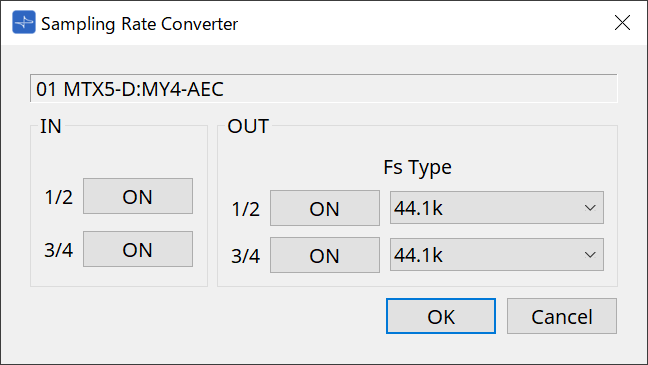
15.7.8. “Sampling Rate Converter” dialog box
Click to open "Sampling Rate Converter" in the context menu of the "Slot In" or "Slot Out" component editor.
Here you can turn on/off the SRC (Sampling Rate Converter) of the MY4-AEC or MY8-AE96S that is installed in the device’s slot, and specify the word clock setting of the output.
-
[ON] button
Switches the SRC on/off. The button also shows the on/off status. -
[Fs Type] box (MY4-AEC only)
This selects the word clock that will be output from the MY4-AEC when SRC is on.
If you select AES/EBU_IN_CH1/2, the word clock that is received at input 1/2 of the MY4-AEC will be output. If you select AES/EBU_IN_CH3/4, the word clock that is received at input 3/4 of the MY4-AEC will be output. -
[OK] button
Applies the settings and closes the dialog box. -
[Cancel] button
Closes the dialog box without applying the settings.
15.8. Alert list
The alerts generated by MRX7-D/MTX5-D/MTX3 units, and their significance and the appropriate actions, are listed below.
If the problem is not solved, please contact your Yamaha dealer.
|
Alert
number |
Meaning | Response |
|---|---|---|
|
01–09 |
The device has not started up correctly. |
Turn the power off, then turn on after waiting at least 6 seconds. If this does not solve the problem, please initialize the memory. Should this also fails, contact your Yamaha dealer. |
|
10 |
The internal backup battery has been completely exhausted or is not installed. |
When you turn off the power, the current settings will be lost, and will return to the default values. Please stop use immediately, and contact your Yamaha dealer. |
|
11 |
The internal backup battery has run extremely low, and it is possible that the internal memory has been cleared. |
When you turn off the power, the current settings will be lost, and will return to the default values. Please stop use immediately, and contact your Yamaha dealer. |
|
12 |
The internal backup battery has only a small amount of power remaining. |
This does not affect the operation of the device. However, if you continue using the device, the settings may be lost and reset to the default values. Contact your Yamaha dealer as soon as possible. |
|
13 |
A problem has occurred with the internal clock, and it has been initialized (January 1, 2000, 0:00). |
If this occurs each time you turn on the power, it is possible that the internal backup battery has run down or that the device has malfunctioned. Contact your Yamaha dealer.
|
|
14 |
The current preset saved in internal memory has been lost. |
Recall the preset. If this does not solve the problem, contact your Yamaha dealer. |
|
15 |
The settings saved in internal memory have been lost. |
Either the internal backup battery has run low, or the device has malfunctioned. Contact your Yamaha dealer. |
|
20 |
An unsupported Mini-YGDAI card is inserted in the slot, or the inserted Mini-YGDAI card has malfunctioned. |
Replace the card with a supported Mini-YGDAI card or check that the supported Mini-YGDAI card is working correctly in another Host. |
|
21 |
The word clock leader has become unlocked. |
Make sure that the word clock signal is being input correctly. |
|
22 |
The digital signal being input to the [YDIF IN] connector is not synchronized to the word clock of this device. |
Make sure that YDIF cables are properly connected.
|
|
23 |
The digital signal being input to the [YDIF IN] connector is not continuously synchronized to the word clock of this device. |
|
|
24 |
The digital signal being input to the slot is not synchronized to the word clock of this device. |
Either input a signal that is synchronized, or specify the slot as the word clock leader. |
|
25 |
The digital signal being input to the slot is not continuously synchronized to the word clock of this device. |
|
|
26 |
The digital signal being input to the Dante connector is not synchronized to the word clock of this device. |
Either input a signal that is synchronized, or specify the Dante as the word clock leader. |
|
27 |
The digital signal being input to the Dante connector is not continuously synchronized to the word clock of this device. |
|
|
28 |
The Dante sampling frequency has been changed to match the word clock leader of this unit. |
Check the word clock setting of this unit. Then set the sampling frequency of the Dante network. |
|
30 |
There is a problem with the connection of the [YDIF IN] connector. |
Make sure that YDIF cables are properly connected.
|
|
40 |
Duplicate IP addresses. |
Change the IP addresses so that there are no duplicates. |
|
41 |
IP address was not set within 60 seconds of startup. |
Please check rear panel DIP switch 6 (IP Setting). If DIP switch 6 is set to “PC,” use ProVisionaire Design or DHCP server to specify the device IP address. |
|
42 |
A device within the MTX system was not found on the network. |
Power-on all devices in the system, and make sure that they are correctly connected to the network. |
|
43 |
Too many devices are connected to the network. |
Reduce the number of devices connected to the network. |
|
46 |
Dante transmission flow count exceeded the limit. |
Maximum Dante Flow rate exceeded. Try changing parts of transmission flows to Multicast using Dante Controller. |
|
50 |
The UNIT ID is set to “00.” |
Set the UNIT ID to something other than “00.” |
|
51 |
Devices with identical UNIT IDs were found connected within the same network. |
Change the UNIT ID so that there are no duplicates. |
|
52 |
A communication error occurred with the [DCP] connection. |
• If an error was shown in the DCP panel, refer to the DCP owner’s manual and take the appropriate action.
|
|
53 |
[The DCP connected to the [DCP] connector has been configured differently from the project settings. |
• Check that the required DCP is connected.
|
|
56 |
SD memory card was not recognized. |
Use an SD memory card that complies with the specifications. |
|
58 |
Unable to play the specified file or folder in the SD player. |
Verify that the specified audio file or folder exists in the SD memory card. There must be at least one playable audio file in the specified folder. |
|
60 |
A preset recall attempt has failed. |
Initialize the memory of the device. If this does not solve the problem, contact your Yamaha dealer. |
|
61 |
The recall could not be executed because the preset to be recalled when the MTX starts up was not found. |
Specify a preset that exists. No sound will be output unless an appropriate preset is recalled. |
|
64 |
The preset could not be recalled. |
• The Preset selected for recall cannot be recalled as no data has been stored to it.
|
|
70 |
Synchronization has not been completed. It may be that synchronization was halted before completion. |
Perform synchronization again using ProVisionaire Design. If this does not solve the problem, initialize the memory of the device and synchronize again. If this also fails, contact your Yamaha dealer. |
|
71 |
The UNIT ID settings when synchronization was performed do not match the current UNIT ID settings. |
Do not change any UNIT ID’s after performing synchronization. If you’ve changed any UNIT ID’s, perform synchronization again. |
|
72 (MRX7-D/MTX5-D) |
Because this device has Dante Device Lock enabled, the settings of device DIP switches and ProVisionaire Design do not match current Dante settings. |
If you have Dante Device Lock enabled, please disable using Dante Controller, review device DIP switch settings and ProVisionaire Design’s Dante settings, and edit as necessary to match the current situation. |
|
80 (MRX7-D only) |
The audio file for the Speech Privacy component does not exist. |
Install it using the Install Speech Privacy File dialog. |
15.9. Component editors
The component editor allows you to set and adjust each component of the selected device.
When you double-click a component in the device sheet, the component editor opens.
Here we explain the MTX-specific component editor. For details about other components, refer to the
"ProVisionaire Design Component Guide"
.

| Number | Component name | Details | Link |
|---|---|---|---|
|
① |
Analog In |
Displays the settings related to the [INPUT] terminal input and the level of the audio signal being input. |
|
|
② |
Stereo In |
Displays the audio signal level being input from the [ST IN] terminal. |
--- |
|
③ |
SD In |
Sends the audio signal that is being played from SD memory. |
--- |
|
④ |
YDIF In |
Displays the audio signal level input from the [YDIF] terminal. |
--- |
|
⑤ |
Dante In(MTX5-D only) |
Sends the audio signal input from the [Dante] terminal. |
--- |
|
⑥ |
Slot In(MTX5-D only) |
Displays the audio signal level being input from the Mini-YGDAI card.
|
|
|
⑦ |
DCP |
Sets the DCP control panel. |
|
|
⑧ |
Input Patch |
Assigns the input source to an input channel. |
--- |
|
⑨ |
Input Ch |
Performs signal processing for input channels. |
|
|
⑩ |
Input Fader |
Adjusts the level of the input channel. |
--- |
|
⑪ |
Fx Fader |
Adjusts the level of the effect return. |
--- |
|
⑫ |
Dugan Automixer |
In speech applications, the MTX3 automatically adjusts the auto-mix gain for input channels 1 to 4, and the MTX5-D automatically adjusts the auto-mix gain for input channels 1 to 8. |
|
|
⑬ |
Insert (MTX5-D only) |
Turns the Mini-YGDAI card insert ON or OFF. |
|
|
⑭ |
Matrix Mixer |
Mixes the input channel signals and sends them to each ZONE. |
|
|
⑮ |
Matrix Out Fader |
Adjusts the level from the matrix mixer to the ZONE. |
--- |
|
⑯ |
Effect |
Adjusts the effect(s). |
--- |
|
⑰ |
Zone |
This screen is used to specify settings related to the PGM1 (MTX5-D only) and to output signals based on the priority of the input signal. |
|
|
⑱ |
From YDIF In |
The input signal from the ④ [YDIF IN] terminal. |
--- |
|
⑲ |
Oscillator |
Outputs the oscillator signal. |
--- |
|
⑳ |
Zone Out Fader |
Adjusts the ZONE output level. |
--- |
|
㉑ |
Router |
Assign signals to output channels. |
|
|
㉒ |
Output Ch |
Performs signal processing on the output channel. |
|
|
㉓ |
Output Fader |
Adjusts the level of the output channel. |
--- |
|
㉔ |
Post on Input Fader |
The output signal from ⑩ [Input Fader] or ⑫ [Dugan Automixer]. |
--- |
|
㉕ |
Post on Zone Out |
The output signal from ⑳ [Zone Out Fader]. |
--- |
|
㉖ |
Output Patch |
Assigns output signals to the various types of output terminals. |
--- |
|
㉗ |
YDIF Out Patch |
Assigns output signals to the [YDIF] terminal. |
--- |
|
㉘ |
Pilot Tone |
Sets the pilot tone. |
|
|
㉙ |
Analog Out |
Displays the settings related to the [OUTPUT] terminal output and the level of the audio signal being output. |
|
|
㉚ |
Dante Out (MTX5-D only) |
Specifies the Dante output-related settings. |
|
|
㉛ |
Slot Out (MTX5-D only) |
Displays the settings related to the Mini-YGDAI card output and the level of the audio signal being output. |
|
|
㉜ |
YDIF Out |
Outputs to the [YDIF] terminal. |
--- |
|
㉝ |
Input DCA Groups |
Sets the DCA group for the input channel. |
|
|
㉞ |
Input Mute Groups |
Sets the mute group for the input channel. |
|
|
㉟ |
Zone DCA Groups |
Sets the DCA group for the ZONE output. |
|
|
㊱ |
Zone Mute Groups |
Sets the mute group for the ZONE output. |
15.9.1. "Analog In" component editor
Here you can make settings to the HA (head amp) of the [INPUT] jack, and view the levels of the audio signals that are being input.

①
Channel index
Indicates the analog input jack number.
②
Level meter
Indicates the analog input level.
③
[GAIN] knob
Adjusts the analog gain of the HA (head amp).
④
[+48V] button
Turns the HA phantom power (+48V) on/off.
![]() Notice
Notice
Be sure to leave this button off if you do not need phantom power.
When turning phantom power on, you must observe the precautions below in order to prevent noise and possible damage to the unit and to external devices.
• Leave this button off if a device that does not support phantom power is connected to the [INPUT] connector.
• Do not connect/disconnect a cable to/from the [INPUT] connector while this button is on.
• Lower the output level to the minimum before turning phantom power on/off.
There is no +48V Active switch. To avoid malfunctions, be sure to set this appropriately for the equipment that is connected.
15.9.2. “MY4-AEC” component editor
Right-click the [Slot in] or [Slot Out] component (MTX5-D only), select the "Mini-YGDAI Card" in the context menu and then select the MY4-AEC card “MY4-AEC ” component will be displayed.
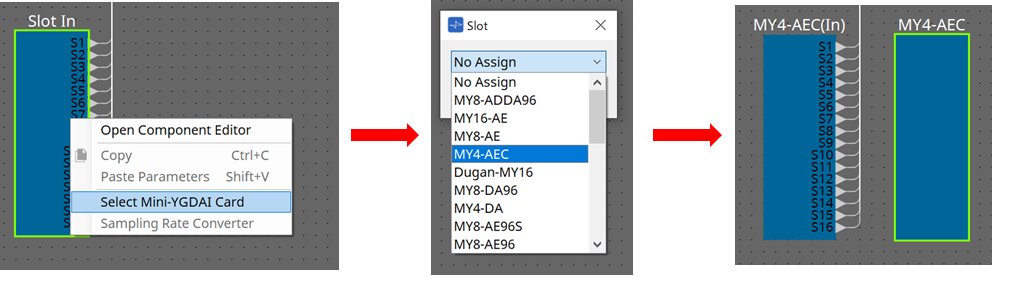
In this screen you can make settings for the signals of the MY4-AEC.
In a teleconferencing system, the local and remote environments are respectively called the Near-end and Far-end.
The MY4-AEC’s acoustic echo canceller (AEC) determines the echo component included in the mic input signal by using the signal from the Far-end as the reference signal, and subtracts only the
echo component of the Far-end from the mic input signal. This allows clear audio from the Near-end to be transmitted to the other party.
The MY4-AEC’s signals can be specified using the following choices and screens.
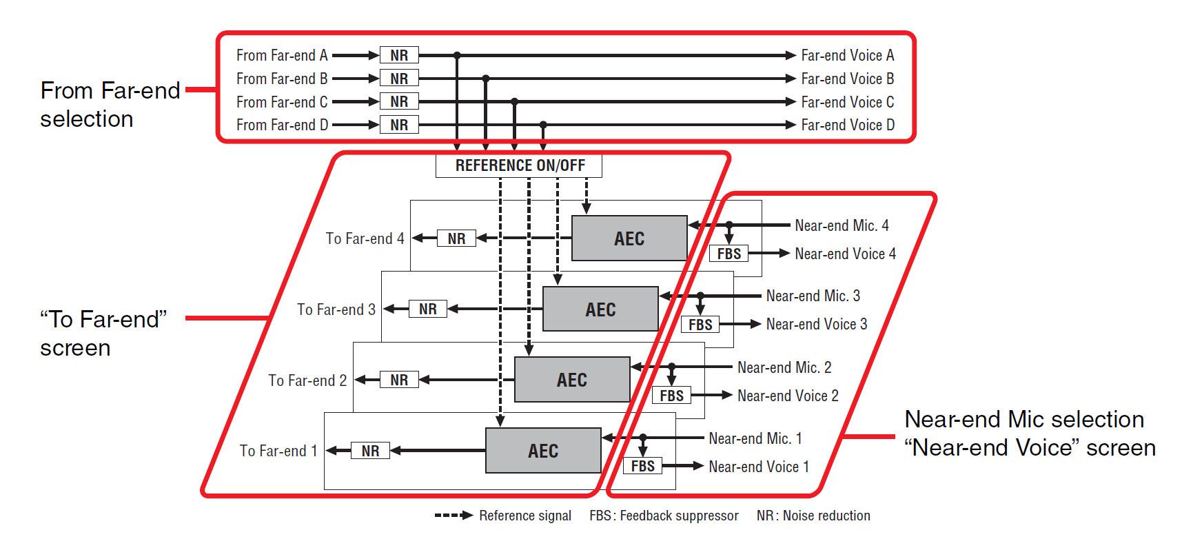
|
From Far-end |
Input signals from the remote location (the other party) |
|
Far-end Voice |
Signals from the remote location reproduced by the speakers of the local location (your side) |
|
Near-end Mic. |
Input signals from local mics |
|
Near-end Voice |
Signals from local mics reproduced by local speakers |
|
To Far-end |
Echo-cancelled signals of local mics sent to the remote location |
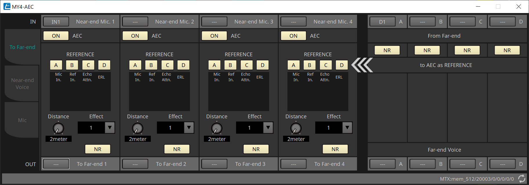
■ “To Far-end” screen
In this screen you can make echo-cancel settings for the mics.
The mic signal after echo-cancellation is output to the remote location.

①
[Near-end Mic] selection buttons
Here you can select the ports for the local mics (Near-end Mic). When you click a port select button, the “Input Patch” dialog box will appear. The button shows the currently selected port.
②
AEC [ON] button
Switches the echo canceller function on/off.
③
REFERENCE [A][B][C][D] button
These buttons select whether the signal specified by the From Far-end selection will be used as the AEC reference signal (REFERENCE).
If multiple signals are selected, they will be mixed.
④ Meters
-
Mic In. meter
Indicates the level of the signal that is input from your own mic (Near-end Mic). -
Ref In. meter
Indicates the level of the reference signal. The most effective echo cancellation will be obtained with a level at which the yellow indicators light occasionally. -
Echo Attn. meter
Indicates the amount of echo cancellation for each channel. Higher levels indicate that the echo canceller is working. -
ERL meter
ERL Indicates the ERL (Echo Return Loss = the level of the audio that is output from the speaker and re-input to the mic). Echo cancellation will work most effectively if you adjust the position of the speaker and mic so as to minimize this level.
⑤
[Effect] list box
Specifies the amount of echo cancellation. Higher numeric values allow more echoes to be cancelled. However, the audio quality will decrease correspondingly, so you should consider the balance between these factors as you make the adjustment.
⑥
[NR] button
These are on/off switches for the noise reduction function which removes steady-state noise such as produced by a projector or air conditioner in the local location. We recommend that you leave these on.
⑦
[Distance] knob
This specifies the distance between the installed mic and speaker in units of meters. If multiple mics and speakers are connected, specify the distance between the mic and speaker that are closest to each other. If the distance is 2 m or less, set this to 2.
⑧
[To Far-end] channel select button
This button selects the output destination for the audio signals that are output to the remote location (Far-end). Click the button to open the “Output Patch” dialog box.
⑨
[From Far-end] signal selection buttons
These open the “Input Patch” dialog box, where you can select the audio signals from the remote location (From Far-end). The button shows the currently selected port or channel.
⑩
[NR] button
These are on/off switches for the noise reduction function which removes steady-state noise such as produced by a projector or air conditioner in the remote location. We recommend that you leave these on. The audio signal after noise reduction will be the reference signal (REFERENCE).
⑪
[Far-end Voice] selection buttons
These buttons select the output destinations for the audio signals that are output to the speakers of the local location. Click a button to open the “Output Patch” dialog box. The button shows the currently selected channel.
| It is assumed that the Far-end Voice will be mixed with the Near-end Mic and output from the speakers. Therefore as seen from the MY4-AEC, the Far-end Voice is output to an input channel of the MTX. |
■ “Near-end Voice” screen

In this screen you can make settings for the FBS (Feed Back Suppressor) that is built into the MY4-AEC.
①
FBS [ON] button
This turns the feedback suppressor function on/off.
The FBS of the MY4-AEC uses the dynamic method of finding the constantly changing feedback points and updating the filter settings accordingly.
This is reset when the MTX5-D is powered-off, and will return to a state in which no notch filter is inserted.
②
[Width] list box
Here you can specify the rejection width of the notch filter that is inserted at the frequency where feedback is detected. Choose a narrower rejection width if the feedback suppressor causes unwanted changes in the character of the sound. A setting of “1/93” is the narrowest setting for the notch filter. However in this case, the feedback suppressor may be less effective.
③
[Depth] list box
Here you can specify the amount of rejection applied by the notch filter that is inserted at the frequency where feedback is detected. A setting of “–18” produces the strongest suppression of feedback. However in this case, you may notice more change in the character of the sound.
④
[Near-end Voice] channel select button
This button selects the output destination for the audio signal that is output locally (Near-end Voice). Click the button to open the “Output Patch” dialog box.
■ “Mic” screen
When using a mic equipped with a PTT (Push To Talk) switch, a small amount of noise may be heard while the PTT switch is off. If this noise is input to the AEC, the AEC will mistakenly learn the noise, causing an echo when the PTT switch is turned on to resume speaking. In this screen you can make settings and specify the type of mic to prevent this from occurring.

①
PTT [ON] button
If this is on, and the input level from the local mic (Near-end Mic) falls below the value specified in PTT Threshold, the system will determine that the PTT switch of the local mic has been turned off, and will stop AEC learning. We recommend
that you leave this on.
②
Mic In. meter
This indicates the level of the signal that is input from the local mic (Near-end Mic). This meter will also indicate the level of the noise that occurs when the PTT button of the mic is off.
③
[PTT Threshold] knob
This knob sets the reference level for AEC learning. If the PTT [ON] button is on, AEC learning will stop when the input signal to the local mic (Near-end Mic) falls below this level; learning will resume when the input signal exceeds this level.
The Mic In. meter indicates the level of the input signal.
④
[Mic. Type] list box
Specify the type of mic that is connected.
Choose “Fixed” for an environment in which the distance between the mic and speaker is fixed, or “Moving” for an environment in which this distance changes, such as when a hand mic is used. Even in an environment in which the distance between the mic and speaker is fixed, choose “Moving” if the echo is obtrusive.
15.9.3. "Input CH" component editor
This screen performs input channel signal processing.
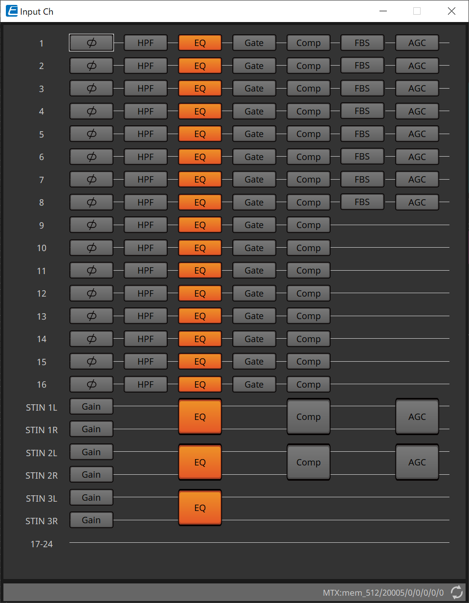
Polarity, "HPF," "EQ," "Gate," "Comp," "FBS," and "AGC" signal processing is performed.
●Screen selection

When you click on a button, you will switch to the setting screen.
For details about adjusting each parameter in the component/editor, refer to the "ProVisionaire Design Component Guide" .
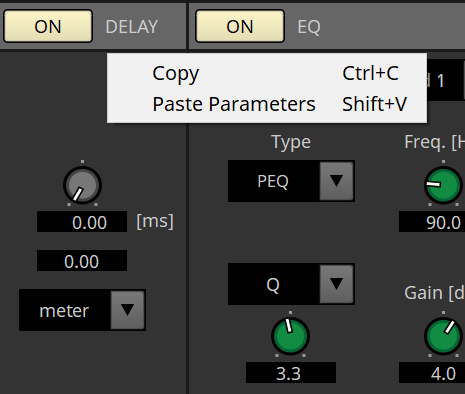
● Operations common to the “INPUT” screens
| Channel settings can be copied to other channels. When you right-click inside an area, a context menu will be displayed. |
15.9.4. "Insert" component editor
This button displays a screen where you can edit the insert on/off setting eight channels at a time.
If this is on, the audio signal will be sent from POST ON to the Mini-YGDAI card installed in [SLOT].
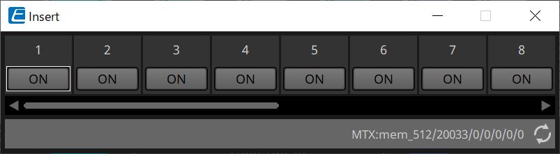
| If no Mini-YGDAI card is installed, or if the installed Mini-YGDAI card does not support insertion, there will be no audio output if this is turned on. |
15.9.5. "Zone" component editor
In this screen you can specify settings for the PGM1, and how input signal priority will control output signals.
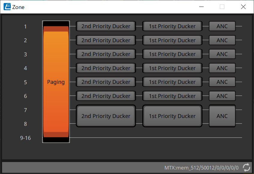
When you click on a button, you will switch to the setting screen.
-
[Paging]
Displays the "Paging" component editor for configuring the PGM1 paging station microphone. -
[2nd Priority Ducker]
[1st Priority Ducker]
Displays the "Priority Ducker" component editor. -
[ANC]
Displays the "Ambient Noise Compensator" component editor.
For more information on Ducker and ANC, please refer to the "ProVisionaire Design Component Guide" .
■ "Paging" component editor (MTX5-D only)
In this screen you can make settings for the PGM1 paging station microphone.
Paging refers to the function of broadcasting an announcement.
For the workflow of making settings, refer to the
“Workflow for paging settings.”
The SD messages referred to here are standard-format announcements saved on the SD card of the MTX.

①
Paging [ON] button
Turns the paging function on/off.
②
[ZONE GROUP] button
The
"ZONE GROUP" editor
opens when this is clicked.
③
[Settings] button
The
"PGM1/PGX1" editor
opens when this is clicked.
④ PAGING SOURCE settings area
-
Indicator
This is lit if there is a currently-broadcasting PGM1 or SD. -
Channel list box
Selects the paging source. Select the input channel to which a PGM1 or SD is connected. Specify 1st Mic for the input channel of the PGM1 that is specified as 1st Priority.
⑤ ZONE area
-
Indicator
This is lit if there is a zone that is currently broadcasting using a PGM1 or SD message.
⑥
GAIN setting area
Each knob resets to the default value if you click it while holding down the < Alt > key.
In this area, you can make settings related to the line shown in green in the flow depicted below.
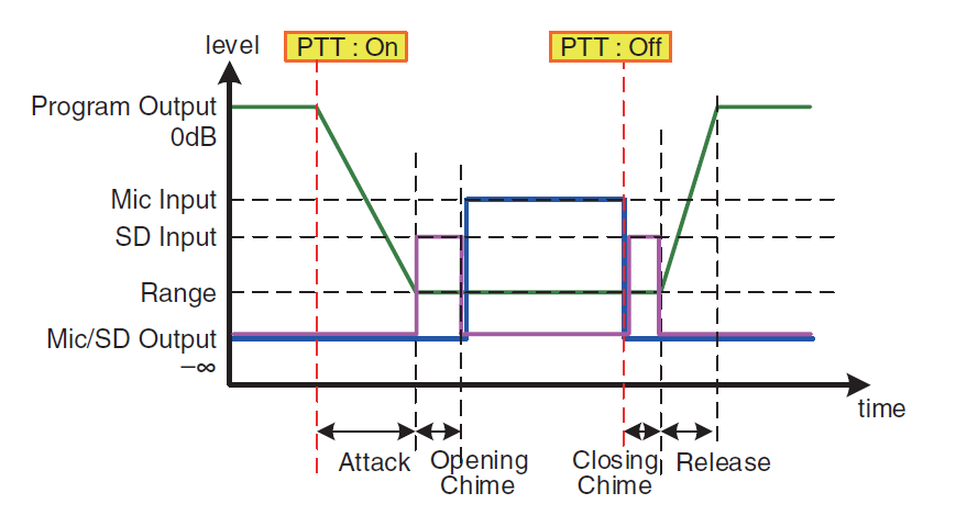
-
[RANGE] knob
Specifies the Program value while the chime is sounding or while the PGM1 is broadcasting. -
[ATTACK] knob
Specifies the time from when the PGM1’s PTT turns on until the program decreases to the RANGE value. -
[RELEASE] knob
Specifies the time from when the broadcast or the closing chime finishes playing until the program returns to its original level.
■ "ZONE GROUP" editor

①
Zone name
Indicates the zone name.
②
Group name
Indicates the group name.
③
ZONE GROUP matrix
Specify a zone group if you want a single zone/message select button of a PGM1/PGX1 to broadcast to multiple zones. Click on the matrix to select Zones to add to the Zone Group. You can specify up to 24 zone groups.
④
[CLEAR] button
Clears the ZONE GROUP that had been set.
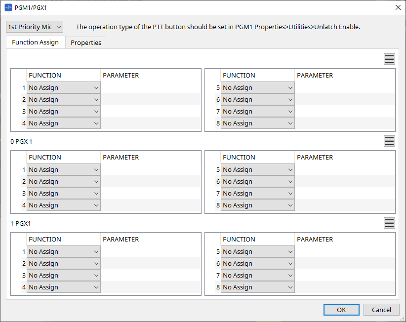
■ "PGM1/PGX1" editor
Here you can make assignments for the zone/message select buttons of the PGM1 and PGX1, and make settings for the PTT button.
-
PGM1 select list box
Select the PGM1 unit for which you want to make settings.
| PGM1/PGX1 settings can be made even if PGM1 is not connected to the MTX itself. Please connect PGM1/PGX1 properly during operation. |
-
[Function Assign] tab
Here you can assign functions to the zone/message select buttons of the PGM1 or PGX1.
“FUNCTION” provides the following choices.-
[No Assign]
No function is assigned to the button. -
[Zone]
Selects/de-selects the zone to broadcast.
When selected, the zone/message indicator is lit. -
[Zone Group]
Selects/de-selects multiple zones to broadcast in a single operation.
Set the zone group using the “ZONE GROUP” editor .
The zone/message indicator is lit when broadcast is possible to all zones that are registered in the group. -
[SD Message]
Selects the file of the SD card to play. -
[All Zone Off]
De-selects all zones/zone groups.
This does not affect the selection status for the zones/zone groups of other PGM1/PGX1 units. -
[All Zone On/Off]
Selects/de-selects all zones/zone groups.
This does not affect the selection status for the zones/zone groups of other PGM1/PGX1 units.
The zone/message indicator is lit when broadcast is possible to all zones/zone groups.
-
-
Menu button (
)
Click the menu button to execute the following functions.-
[Copy]
Copies the FUNCTION and PARAMETER settings of the corresponding device to the copy buffer. -
[Paste]
Pastes the FUNCTION and PARAMETER settings from the copy buffer, overwriting them onto the corresponding device. -
[Clear]
Initializes the FUNCTION and PARAMETER settings of the corresponding device.
-
-
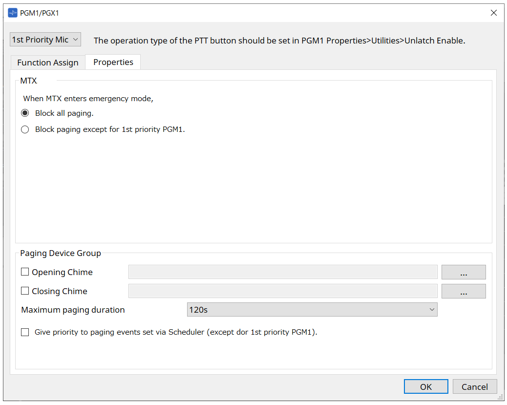
[Properties] tab
Here you can make settings for the operation of the PCM1.
-
MTX
-
[Stop all broadcast.] option button
If this is selected, paging broadcast including the scheduler will be stopped when the MTX is in emergency mode. -
[Stop broadcast except for 1st Priority PGM1] option button
If this is selected, paging broadcast will be possible only for the 1st Priority PGM1 when the MTX is in emergency mode.
-
-
Paging Device Group
-
[Opening Chime]/[Closing Chime] check boxes
If these check boxes are selected, you can make settings for the opening chime and/ or closing chime. Click the button at right to specify the chime file that will play. This setting is shared by the PGM1 (Paging Device Group) units that are connected to the same MTX. -
[Maximum paging duration] list box
Selects the time after PTT is turned on until it is automatically turned off. If a message is being played back, it will not turn off even if the specified time is exceeded. This setting is shared by the PGM1 units that are connected to the same MTX. -
[The scheduler’s paging events are broadcast with higher priority than PGM1. Paging events have a lower priority than 1st Priority PGM1.] check box
If this check box is selected, the priority order will be “1st Priority PGM1 > events > normal PGM1.” If this check box is cleared, the priority order will be “1st Priority PGM1 > normal PGM1 > events.”
-
-
[OK] button
Saves the settings and closes the dialog box. -
[Cancel] button
Discards the settings and closes the dialog box.
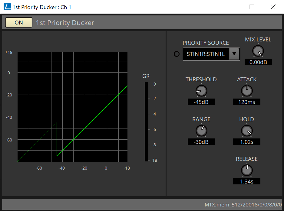
■ "PRIORITY DUCKER" component editor
You can make ducker settings.
The ducker is a function that temporarily reduces the input from one channel when an audio signal is input to another specified input channel, allowing the audio from the specified channel to be heard clearly. The priority order is as follows: “PRIORITY SOURCE” of the “1st PRIORITY” > “PRIORITY SOURCE” of the “2nd PRIORITY” > MATRIX Out signal.
-
[PRIORITY SOURCE] list
Selects the input signal for the ducker.
Select [ANC Bus] if you want the mixed signal to be the high-priority audio. The mix of audio signals to the ANC bus can be created in the "Matrix Mixer" component editor.
For details about other parameters, refer to the "ProVisionaire Design Component Guide" .
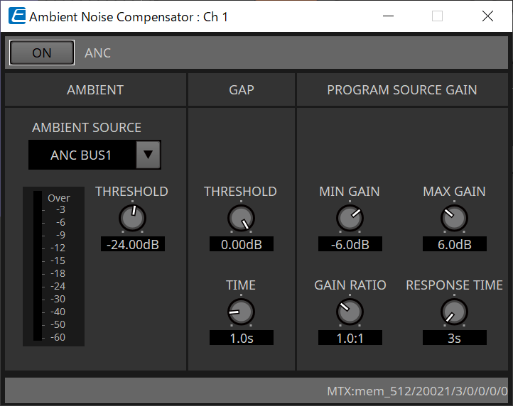
■ "Ambient Noise Compensator" component editor
In this editor you can make settings for the “Ambient Noise Compensator” (subsequently called “ANC”). ANC is a function that boosts or attenuates the output signal from the MTX according to the level that is being input via an ambient noise detection mic. The ANC function provided by the MTX is a gap-type ANC that detects silent intervals such as between songs, detects the noise level during those intervals, and varies the level accordingly.
For details about parameters, refer to the "ProVisionaire Design Component Guide" .
15.9.6. "Output CH" component editor
This screen performs output channel signal processing.
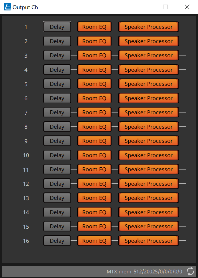
This performs the "Delay," Room EQ," and "Speaker Processor" signal processing.
●Screen selection

When you click on a button, you will switch to the setting screen.
For details about adjusting each parameter in the component editor, refer to the "ProVisionaire Design Component Guide" .
● Operations common to the “OUTPUT” screens
|
You can copy channel settings to other channels.
When you right-click within the area, context menu will appear. |
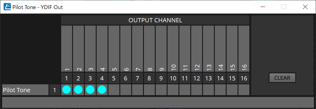
15.9.7. "Pilot Tone" component editor
You can make settings to specify whether a pilot tone is output from digital output.
When the PILOT TONE [ON] button is turned on, the pilot tone is set to the YDIF or Dante output channel that has been assigned to pilot tone output.

①
PILOT TONE [ON] button
Sets the ON/OFF status of the pilot tone function. If OFF, the pilot tone will not be sent even if the ”YDIF” or "DANTE” is set to ON.
②
Freq.
Indicates the center frequency of the pilot tone. This is fixed at 20 kHz.
③
[LEVEL] knob
Specifies the level of the pilot tone.
④
YDIF button
The screen to set the pilot tone output to YDIF opens when this is clicked.
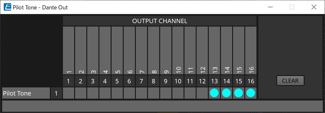
⑤
DANTE button (MTX5-D only)
The screen to set the pilot tone output to DANTE opens when this is clicked.
15.9.8. "Analog Out" component editor
Here you can make settings for the [OUTPUT] jack outputs, and view the levels of the audio signals that are being output.

①
Channel index
Indicates the analog output jack number.
②
Level meter
Indicates the analog output level.
③
[GAIN] knob
Adjusts the output gain.
④
[INV] button
Switches the polarity of the output signal.
15.9.9. "Slot Out" component editor
Here you can make settings for the Mini-YGDAI card outputs, and view the levels of the audio signals that are being output.

①
Channel index
Indicates the output jack number.
②
Level meter
Indicates the output level.
③
[GAIN] knob
Adjusts the output gain.
④
[INV] button
Switches the polarity of the output signal.
15.9.10. "DCA Groups"/"Mute Groups" component editor
This is a component editor to control the level and mute for multiple channels at the same time.
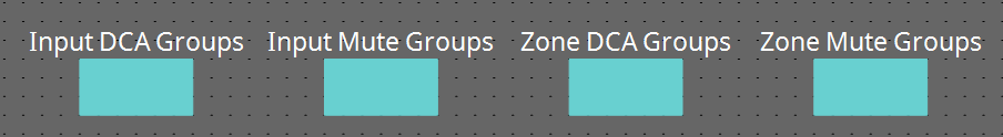
These component editors can register 8 groups for the DCA group and mute group for the input channels and 8 groups for the DCA group and mute group for the ZONE output.
In the DCA groups, the input level or output level of multiple channels can be controlled simultaneously with a single knob.
The mute group can be used to turn multiple channels ON or OFF simultaneously.
-
"Input DCA Groups" component
Displays the editor to set the DCA group for the input channel. -
"Input Mute Groups" component
Displays the editor to set the mute group for the input channel. -
"Zone DCA Groups" component
Displays the editor to set the DCA group for the ZONE output. -
"Zone Mute Groups" component
Displays the editor to set the mute group for the ZONE output.
■
"Input DCA Groups" component/"Zone DCA Groups" component
A screen for the "Input DCA Groups" component is shown below, but the "Zone DCA Groups" component screen has the same layout.

①
[Clear] button
This button clears all channels assigned to the corresponding group.
②
Assignment channel matrix
This matrix lets you assign channels to DCA groups.
The group names are shown on the vertical axis, and the names of the channels that can be assigned are shown on the horizontal axis. Click an intersection to assign a channel to a group.
③
[Level] knob
Adjust the level of each DCA group.
■
"Input Mute Groups" component/"Zone Mute Groups" component
A screen for the "Input Mute Groups" component is shown below, but the "Zone Mute Groups" component screen has the same layout.

①
[Mute] group main button
These buttons turn each mute group on/off.
15.10. Workflow for paging settings
Up to four PGM1 units can be connected to one MTX5-D unit. One PGM1 becomes the 1st Priority Mic and can be broadcast with priority over other PGM1s.
Here’s an example of connecting four PGM1 units to the MTX5-D.
The mic that has higher broadcast priority than the other mics is called the 1st Priority Mic (Unit ID = 60). Patch its output to the MTX5-D’s Dante Input 1Ch.
Patch Mic2-4 (Unit ID=61-63) to Dante Input 2Ch-4Ch of MTX5-D similarly.
Configure Dante settings with Dante Controller.
-
In the “Project” sheet, place the MTX5-D.
-
Select the MTX5-D placed on the “Project” sheet.
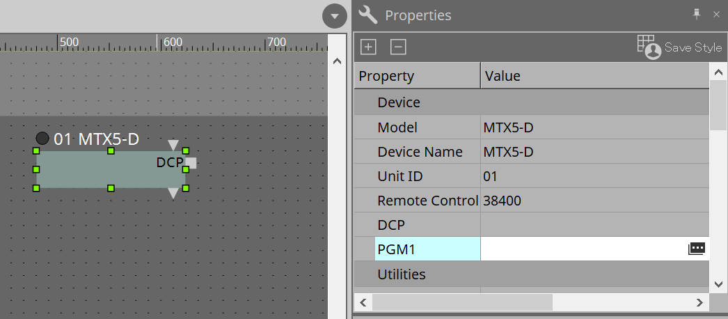
To display the "PGM1" dialog, first click the „Value“ column of the "PGM1" in the "Property" area, then click on
.
-
Specify the Unit ID (60 to 63) of PGM1.
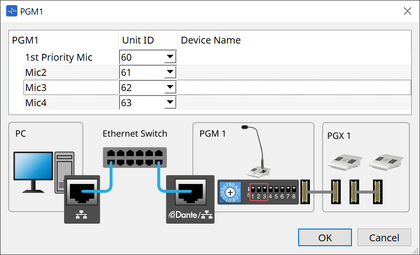
-
Open the MTX5-D’s “Input Patch” component editor.
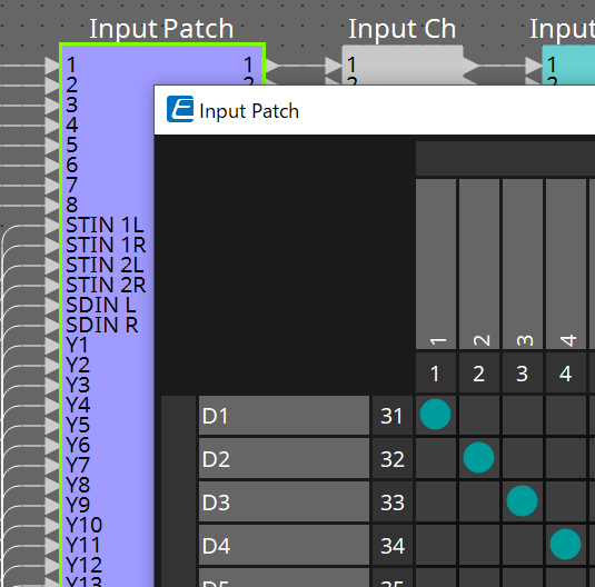
Assign D1 to Input Channel 1.
Assign D2-D4 to input channels 2-4 in the same way.
-
Open the MTX5-D’s “ZONE” component -→ “Paging” component editor.
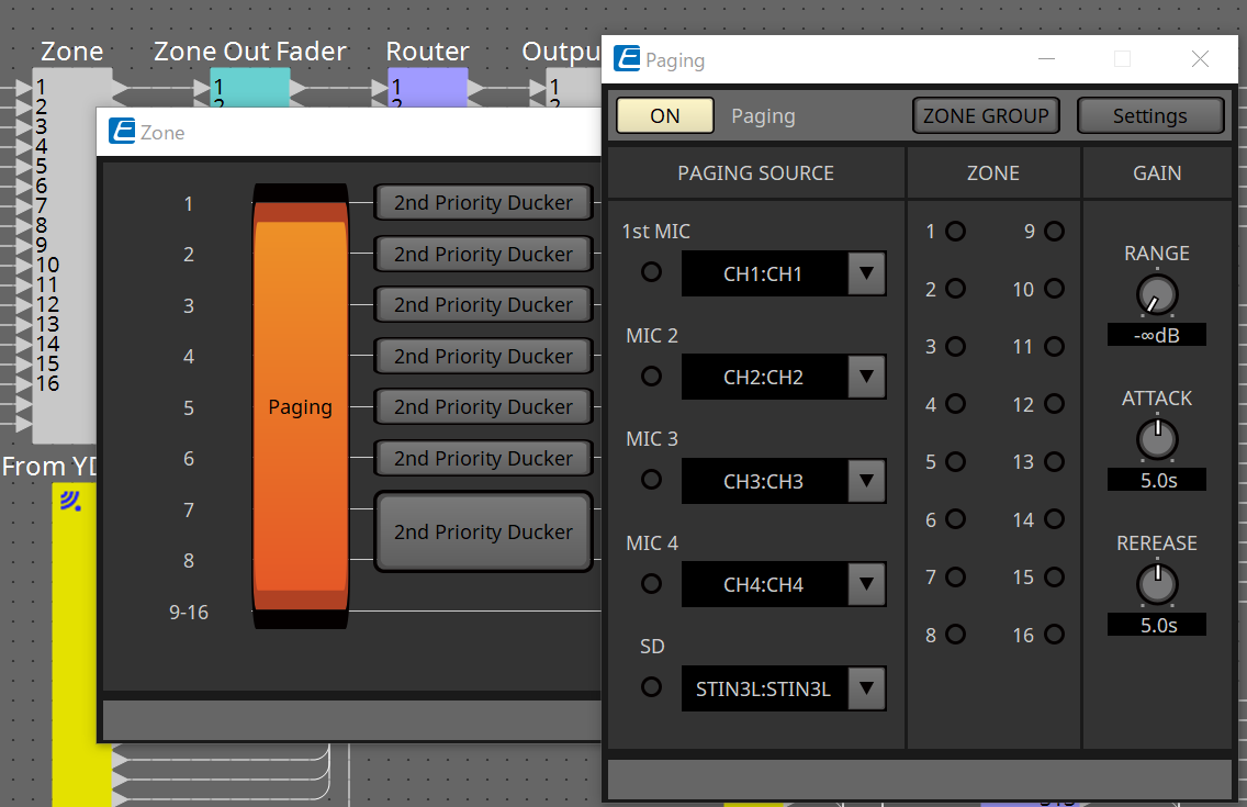
Select “CH1:CH1” for 1st Mic of PAGING SOURCE.
Select others as well.
-
Assign functions to buttons in the "PGM1/PGX1" editor that appears when you click the [Settings] button.
As necessary, set the ZONE GROUP in the “ZONE GROUP” editor that appears when you click the [ZONE GROUP] button.For the "PGM1/PGX1" editor and "ZONE GROUP" editor, refer to the respective explanations.
|
The initial setting of PGM1 Properties -→ Utilities -→ Unlatch Enable is "OFF".
The following procedure is required to change the Unlatch Enable setting and reflect it in PGM1. 1. Install Bonjour Print Service on your computer so that ProVisionaire Design can find PGM1. 2. Place PGM1 on the "Project" sheet. Specify the Unit ID set in "3" when placing. |
The settings will be reflected when synchronizing.