Power Amplifiers XMV-series
19. Power Amplifiers XMV-series
19.1
Overview
19.2
"Project" sheet
19.3
Tuning Sheet
19.4
Device sheet screen configuration
19.5
Context Menu
19.6
Alert list
19.7
Component editors
19.1. Overview
The XMV series is a Class D power amplifier that offers high efficiency while also incorporating functions optimized for commercial spaces. In addition to analog inputs and outputs, the system is equipped with the newly developed "YDIF" digital audio format or "Dante" network audio. The YDIF-compatible models that are connected using Ethernet cables simplify setup, while the Dante models enable high-quality digital transmission in large-scale facilities.
19.2. "Project" sheet
This is the sheet on which devices are placed.
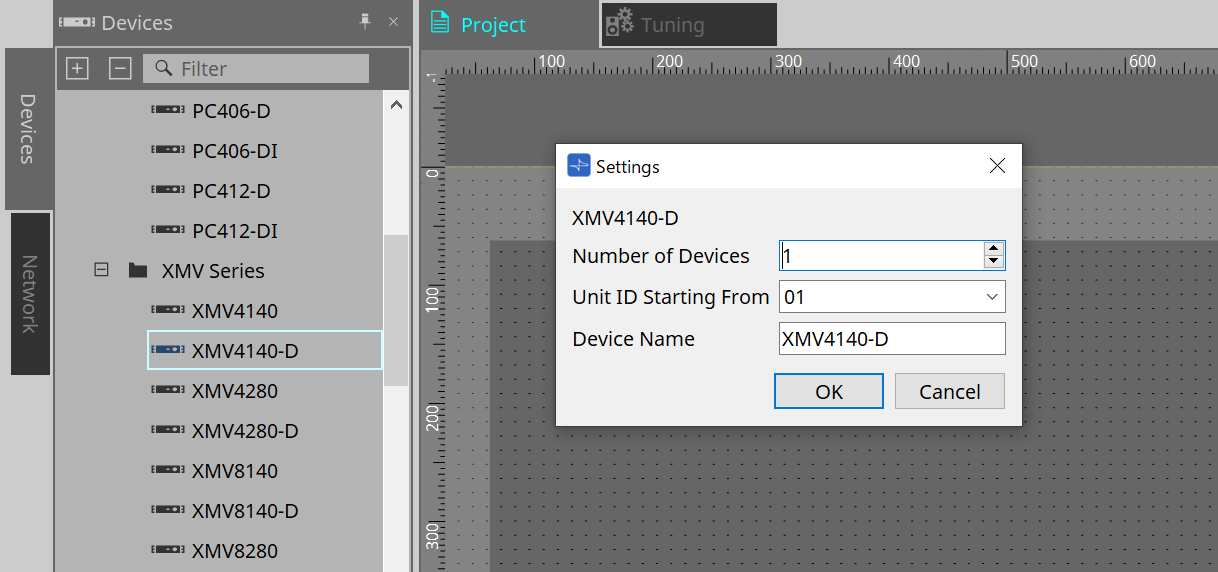
When placing devices, the Settings screen shown below will be displayed.
-
Number of Devices
Selects the number of XMV series units placed on the sheet. -
Unit ID Starting From
You can select the starting number for the device Unit IDs. -
Device Name
The device name can be displayed and edited.
19.2.1. "Properties" area
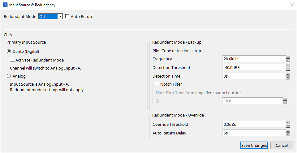
"Input Source & Redundancy"
Here you can specify for each channel whether the input source to the XMV will be digital or analog. If the input source is specified as digital, you can specify that the input source will switch from digital to analog when a pilot tone or analog input is detected. Here we explain the screen for when the digital input is Dante.
When you click on the Value field for each channel in the Properties Area "Input Source&Redundancy," and then click the "…" that is displayed, the "Input Source & Redundancy" dialog will be displayed.
-
[Redundant Mode] list box
Selects the redundancy method.-
[Off]
Redundancy is disabled. -
[Backup]
Switch to analog input when the pilot tone of the digital input is interrupted due to a broken connection or other problem. -
[Override]
Switch to the analog input when analog audio is detected.
-
-
[Auto Return] check box
If this check box is selected, operation will be as follows.-
In the case of Backup mode
When the digital input recovers, the input source is switched from analog to digital. -
In the case of Override mode
When the analog input falls below the threshold value, the input source is returned from analog to digital.
-
-
Channel index
Shows the input channel number for which to make settings. -
"Primary Input Source" area
Here you can specify for each channel whether the input will be digital or analog.-
[YDIF (Digital)]/[Dante (Digital)] option button
The signal of the corresponding channel is taken from YDIF or Dante.
To specify the Dante patching, make settings in Dante Controller. -
[Active Redundant Mode] check box
If this check box is selected, the redundancy function is enabled.
The [Redundant Mode] list box determines the redundancy mode. If [Off] is selected, the redundancy function is disabled even if this check box is selected. -
[Analog] option button
The signal is taken from the analog input jack of the corresponding channel.
-
-
"Redundant Mode - Backup" area
Here you can specify how the pilot tone is detected for each channel.-
[Frequency] spin box
Specifies the center frequency of the pilot tone. -
[Detection Threshold] spin box
Specifies the input level threshold value for the pilot tone. Input that exceeds the threshold value is considered to be the pilot tone.-
[Detection Time] spin box
Specifies the detection time for the pilot tone. If the pilot tone can not be detected for the specified time interval, it is determined that the input has ceased. -
[Notch Filter] check box
If this check box is selected, a notch filter is enabled to eliminate the frequency component of the pilot tone so that the pilot tone is not output from the amp.
-
-
[Q] spin box
Specifies the width of the frequency band for the notch filter.
-
-
"Redundant Mode - Override" area
Here you can specify the conditions under which each channel will switch to the analog input in Override mode.-
[Override Threshold] spin box
Specifies the threshold value for the analog input. When the threshold value is exceeded, the input source will switch to analog. -
[Auto Return Delay] spin box
If the [Auto Return] check box is selected, this specifies the time after the analog input falls below the threshold value until the input is switched back to the digital input.
-
-
[Save Changes] button
Saves the settings and closes the dialog box. -
[Cancel] button
Discards the changes and closes the dialog box.
19.3. Tuning Sheet
The Tuning sheet allows you to set parameters (such as EQ and Delay) for grouped channels collectively.
For the sheet details, please refer to the
"Tuning" sheet
.
19.3.1. Link group editor
This is the parameter setting screen for link groups.
This appears when you double-click a link group on the "Tuning" sheet in which a channel of a XMV-series unit is registered, or when you right-click and choose [Open Link Group Editor].
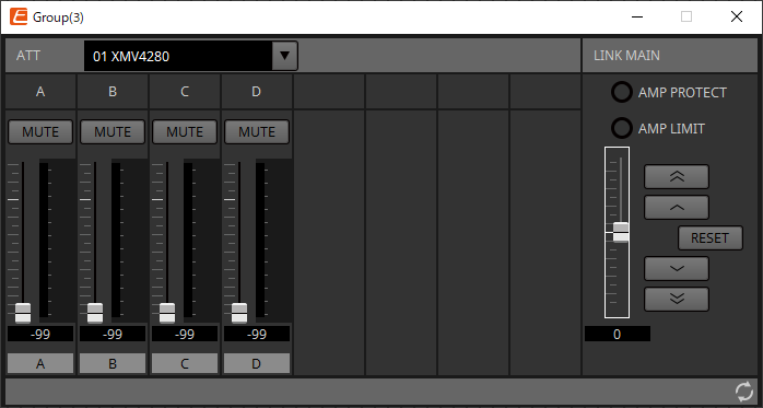
19.3.2. "ATT"
Here you can make collective adjustments to the attenuator of the channels registered in the group.
Use the Main fader to control the attenuator.
The "LINK MAIN" main fader collectively applies a relative adjustment to the attenuator of the channels registered in the group.
For details on the attenuator, refer to
"Power/ATT/Polarity" component editor
.
-
ATT list box
Lists the amps that are registered in the group. -
Channel index
The channel index of the device.
19.3.3. "LINK MAIN"
Applies a relative adjustment to the attenuators within the link group.
-
[AMP PROTECT] indicator
This will light if the protection function of the XMV unit itself is operating. -
[AMP LIMIT] indicator
This will light if the limiter of the XMV unit itself is operating. -
Main fader
Applies a relative adjustment to the attenuators within the link group. The adjustable range is shown above and below in gray.
When you right-click the fader and choose [Match Values], the members of the link group are set to the same attenuator value. -
 button
Raises the main fader by 3 dB. -
 button
Raises the main fader by 1 dB. -
[RESET] button
Moves the main fader to the 0 position. -
 button
Lowers the main fader by 1 dB. -
 button
Lowers the main fader by 3 dB.
19.4. Device sheet screen configuration
When you open the device sheet for an XMV-series device, the device sheet and the "Bird’s Eye view" appear.
When you double-click a component in the device sheet, the component editor opens.

①
Bird’s Eye view
This shows an overview of the sheet.
19.5. Context Menu
The following describes the contents of the context menus that are displayed when you right-click each area.
19.5.1. "Tuning" sheet
The following context menu appears when you right-click the "Tuning" sheet.
| Menu | Content |
|---|---|
|
[Select All] |
[All Link Groups]
|
|
[Close All Editor Windows] |
Closes all editors. |
|
[Snap to Grid] |
If this is checked, objects are placed in alignment with the grid of the sheet. |
19.5.2. Link group in the "Tuning" sheet
The following context menu appears when you right-click a link group, although certain menu items may be present or absent.
| Menu | Content |
|---|---|
|
[Open Link Group Editor] |
Opens the link group editor. For details on the link group editor, refer to each device. |
|
[Open Amplifier Sheet] |
Opens the device sheet of the selected amp. |
|
[Identify] |
Causes the indicators of the amp to flash for several seconds.
|
|
[Delete] |
If a channel is selected, this deletes the channel from the link group.
|
|
[Bring to Front] |
Moves the link group to the foreground. |
|
[Send to Back] |
Moves the link group to the background. |
19.5.3. "Project Devices" area
The following context menu appears when you right-click a device or channel in the "Project Devices" area.
| Menu | Content |
|---|---|
|
[Find] |
Places the focus on the link group in which the device or channel is registered. |
|
[Add to Link Group] |
Registers the amp’s channels in a link group. If the speaker is connected to an amp, this registers the channel of the connected amp. |
19.5.4. "Link Groups" area
The following context menu appears when you right-click an object in the "Link Groups" area.
| Menu | Content |
|---|---|
|
[Find] |
If you right-clicked a device, this places the focus on that device in the link group, and opens the link group component editor.
|
|
[Delete] |
If you right-clicked a channel, this deletes the channel from the link group.
|
19.6. Alert list
The alerts generated by XMV-series units, and their significance and the appropriate actions, are listed below.
A single alert is shown when the event occurs. A continuing alert is shown when the event occurs and when it ends.
Some alerts and information are shown in ProVisionaire Design but not shown on the unit itself.
If the problem is not solved, please contact a Yamaha service center listed at the end of the device’s operating manual.
| Number | Severity | Content | Action | Single/Continuing |
|---|---|---|---|---|
|
Device abnormality |
||||
|
001~008 |
Fault |
The device has not started up correctly. |
Turn the power off, wait at least five seconds, and then turn the power on. If this does not solve the problem, initialize the memory. If the problem is still not solved, contact a Yamaha service center. |
Continuing |
|
10 |
Fault |
The internal backup battery is completely exhausted, or is not installed. |
When you turn off the power, the current settings will be lost and will return to the default values. Immediately stop using the unit, and contact a Yamaha service center. |
Continuing |
|
11 |
Error |
The internal backup battery is extremely low, and the memory may have been lost. |
Continuing |
|
|
12 |
Warning |
The internal backup battery is low. |
The unit will operate correctly, but if you continue using it the settings may be lost and initialized. Contact a Yamaha service center as soon as possible. |
Single |
|
13 |
Fault |
An error occurred in the internal clock, and it has been set to the default value (year 2000, January 1st, midnight). |
If this occurs each time you turn the power on, it may be that the internal backup battery has run low or that the unit has malfunctioned. Contact a Yamaha service center. If this occurs only once, an abnormality was detected in the value of the clock setting and it has been initialized; use "Clock" dialog box to set the time. |
Continuing |
|
15 |
Fault |
The settings saved in internal memory have been lost. |
It is possible that the internal backup battery is low, or that the unit may have malfunctioned. Contact a Yamaha service center. |
Continuing |
|
16 |
Fault |
It might be that the internal memory of the unit has malfunctioned. |
Contact a Yamaha service center. |
Continuing |
|
21 |
Error |
The digital signal that is selected as the word clock leader is unlocked. |
Check whether the word clock signal is being input correctly. |
Continuing |
|
22 |
Error |
The digital signal being input to the [YDIF IN] connector is not synchronized to the word clock of this unit. |
Check whether the cable is connected correctly.
|
Single |
|
23 |
Error |
The digital signal being input to the [YDIF IN] connector is not continuously synchronized to the word clock of this unit. |
Continuing |
|
|
30 |
Error |
There is a problem with the connection of the [YDIF IN] connector. |
Check whether the cable is connected correctly.
|
Continuing |
|
40 |
Error |
The IP address is conflicting. |
Set the IP address so that it does not conflict. |
Continuing |
|
41 |
Warning |
The IP address was not established within 60 seconds of start-up. |
If the device’s DIP switch 6 (IP SETTING) is set to "PC," use the DHCP server to specify the IP address. |
Continuing |
|
43 |
Error |
Too many devices are connected to the network. |
Reduce the number of devices that are connected to the network. |
Single |
|
46 |
Error |
The Dante transmission flow number limit has been exceeded. |
Reduce the flow number, for example by using Dante Controller to change part of the transmission flow to multicast. |
Single |
|
50 |
Error |
The UNIT ID is set to "00." |
Set the UNIT ID to something other than "00." |
Continuing |
|
51 |
Error |
Another device with the same UNIT ID was found connected to the same network. |
Set the UNIT ID so that it does not conflict. |
Continuing |
|
72 |
Error |
Because Device Lock has been specified for Dante, the DIP switch setting does not match the Dante setting. |
If Device Lock is specified, either cancel it from Dante Controller, or reconsider the DIP switch setting so that it is set correctly for the current state. |
Continuing |
|
100 |
Fault |
The power supply was shut down because a direct current component was detected at the speaker output jack. |
It is likely that the unit has malfunctioned; contact a Yamaha service center. |
Continuing |
|
101 |
Fault |
The power supply was shut down because the power supply temperature exceeded the rated value. |
Turn off the power, wait for the power supply to cool, and then turn the power on again. Lower the output level, since continuous high wattage output will cause high temperatures. If the temperature is still high, check whether dust or foreign matter might be clogging the cooling fan intake, and clean the intake if necessary. |
Continuing |
|
103 |
Error |
The power supply has been shut down by the protection circuit. |
Because a high-load situation has continued, you should lower the output level. Refer to the owner’s manual for the reason that protection was activated. |
Continuing |
|
104 |
Error |
The protection circuit has activated, and output [ch*] is muted. |
Continuing |
|
|
105 |
Fault |
The output was muted because a short was detected in speaker output jack [ch*]. |
It may be that the + and - of the speaker output jack have shorted, or that the connected speaker has malfunctioned. |
Single |
|
106 |
Warning |
The temperature of the amp section (heat sink) has changed, causing the following speaker output status. (
*)
|
Lower the output level, since continuous high wattage output will cause high temperatures. If the temperature is still high, check whether dust or foreign matter might be clogging the cooling fan intake, and clean the intake if necessary. |
Single |
|
Device information |
||||
|
200 |
Information |
The power has turned on. |
— |
Single |
|
201 |
Information |
The power has turned off. |
— |
Single |
|
202 |
Information |
Firmware update has been completed. |
— |
Single |
|
203 |
Information |
Initialization has been executed. |
— |
Single |
|
204 |
Information |
Panel lock has been defeated. |
— |
Single |
|
205 |
Information |
The IP address has been established. |
— |
Single |
|
206 |
Information |
The network IP address has been allocated while operating with the DHCP server. |
— |
Single |
|
207 |
Information |
The network IP address has been released while operating with the DHCP server. |
— |
Single |
|
211 |
Information |
Synchronization between the Editor and the devices has begun. |
— |
Single |
|
Amp information |
||||
|
102 |
Information |
The protection circuit has caused the limiter [ch*] to operate. |
Because a high-load situation has continued, you should lower the output level. Refer to the owner’s manual for the reason that protection was activated. |
Continuing |
|
110 |
Error |
The Redundant Backup function has operated, and channel * has switched to analog input. |
There is a problem with the digital signal. Check the connection of the digital circuit, and check whether a pilot tone signal is being input. |
Continuing |
|
219 |
Information |
The Power Amp Mode was changed. |
— |
Single |
|
226 |
Information |
The Redundant Override function has operated, and channel * has switched to analog input. |
— |
Continuing |
19.7. Component editors
The component editor allows you to set and adjust each component of the selected device.
When you double-click a component in the device sheet, the component editor opens.
This section describes the XMV series component editor, and the dialogs and windows that are closely associated with the components. For details about other components, refer to the
"ProVisionaire Design Component Guide"
".
Dante model

| No. | Component name | Details | Link |
|---|---|---|---|
|
① |
Power |
This sets the power supply standby/ON, mute, polarity, and attenuator. |
|
|
② |
DANTE IN |
Sends the audio signal input from the [Dante] terminal. |
- |
|
③ |
ANALOG IN |
Sends the audio signal input from the analog input terminal. |
- |
|
④ |
Redundancy |
Sets the pilot tone detection setting during Redundant mode. |
|
|
⑤ |
ATT |
This sets the power supply standby/ON, mute, polarity, and attenuator. |
|
|
⑥ |
Polarity |
This sets the power supply standby/ON, mute, polarity, and attenuator. |
|
|
⑦ |
SPEAKER OUT |
Displays the speaker output terminal’s output voltage and output current. |

YDIF model
| Number | Component name | Details | Link |
|---|---|---|---|
|
① |
Power |
This sets the power supply standby/ON, mute, polarity, and attenuator. |
|
|
③ |
ANALOG IN |
Sends the audio signal input from the analog input terminal. |
- |
|
④ |
Redundancy |
Sets the pilot tone detection setting during Redundant mode. |
|
|
⑤ |
ATT |
This sets the power supply standby/ON, mute, polarity, and attenuator. |
|
|
⑥ |
Polarity |
This sets the power supply standby/ON, mute, polarity, and attenuator. |
|
|
⑦ |
SPEAKER OUT |
Displays the speaker output terminal’s output voltage and output current. |
|
|
⑧ |
YDIF IN |
Sends the audio signal input from the [YDIF] terminal. |
- |
|
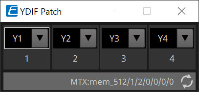
⑨ |
YDIF Patch |
Selects the YDIF audio channel that will be input to each amplifier’s input channel. |
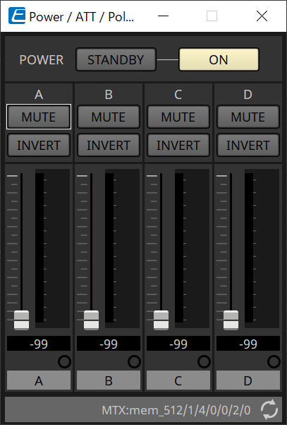
19.7.1. "Power/ATT/Polarity" component editor
This appears when you double-click either a "Power" component, "ATT" component, or "Polarity" component.
-
[STANDBY]/[ON] buttons
Switch the power between standby/on. -
Channel index
Indicates the speaker jack output channel. -
[MUTE] button
Switches mute on/off for the output channel. -
[INVERT] button
Switches the polarity of the output signal. -
Attenuator
Sets the XMV’s output attenuator value. -
Redundancy indicator
This will light if the redundancy function has switched the input to analog. -
Channel name
Indicates the channel name. You can double-click this and edit it.
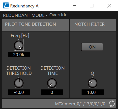
19.7.2. "Redundancy" component editor
This appears when you double-click the "Redundancy" component.
This is the component editor to use if you want to make settings while hearing the sound when the redundancy mode is "Backup."
-
"REDUNDANT MODE"
This indicates the status of redundancy mode. -
"PILOT TONE DETECTION"
Here you can make settings for pilot tone detection.-
[Freq.[Hz]] knob
Specifies the center frequency of the pilot tone. -
[DETECTION THRESHOLD] knob
Specifies the input level threshold value for the pilot tone. Input that exceeds the threshold value is considered to be the pilot tone. -
[DETECTION TIME] knob
Specifies the detection time for the pilot tone. If the pilot tone can not be detected for the specified time interval, it is determined that the input has ceased.
-
-
"NOTCH FILTER"
Here you can make settings for the notch filter that prevents the pilot tone from being output from the amp.-
[ON] button
If this is on, a notch filter is enabled to eliminate the frequency component of the pilot tone so that the pilot tone is not output from the amp. -
[Q] knob
Specifies the width of the frequency band for the notch filter.
-
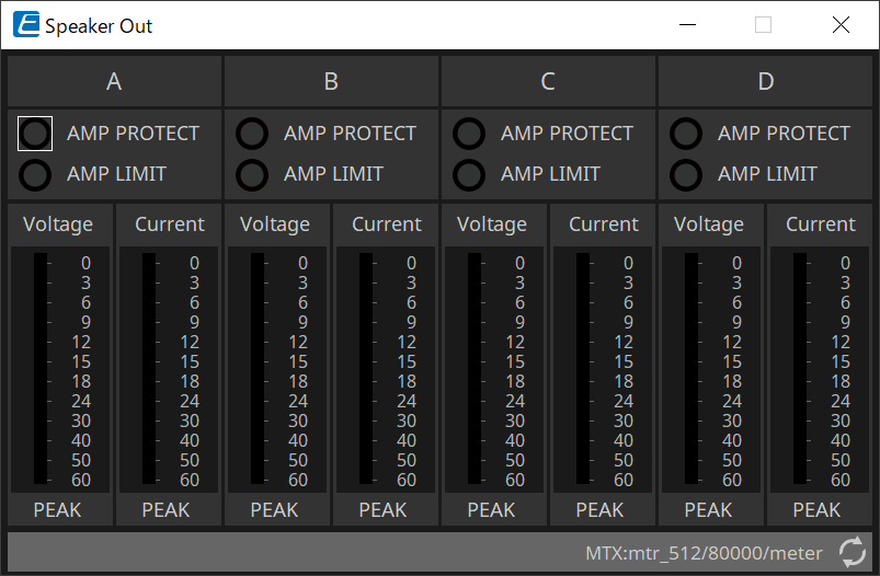
19.7.3. "Speaker Out" component editor
This shows the speaker output jack’s output voltage and output current.
-
[AMP PROTECT] indicator
This will light if the protection function of the XMV unit itself is operating. -
[AMP LIMIT] indicator
This will light if the limiter of the XMV unit itself is operating. -
[Voltage] meter
Shows the output voltage as Peak. -
[Current] meter
Shows the output current as Peak.
19.7.4. "YDIF Patch" component editor
Selects the YDIF audio channel that will be input to each amplifier’s input channel.