Audio Processors DME10/DME7
13. Audio Processors DME10/DME7
13.1
Overview
13.2
"Project" sheet
13.3
Device sheet screen configuration
13.4
Basic use of ProVisonaire Design
13.5
Tool buttons
13.6
"Components" area
13.7
Design sheet
13.8
Design sheet: Audio layer
13.9
Design sheet: Control layer
13.10
Components other than audio or control components
13.11
“Parameter Sets” area
13.12
Parameter Link Group Area
13.13
Temporary Link Group
13.14
“Properties” area
13.15
"Parameters" area
13.16
Context Menu
13.17
Dialog box
13.18
Message List
13.1. Overview
The DME10/DME7 is a freely configurable processor that allows you to place components as desired to freely design a system.
The DME can be operated from an external controller such as DCP/MCP1.
In the device sheet of DME, your workflow consists of freely placing
Components
and then
Compile
the result.
Then, in communication with the DME unit, you’ll use the
Component editor
to edit the parameters.
The Trace Signal Path function allows the signal path to be displayed
(signal path display)
.
By using the Duplicate Port Label function, you the name of the starting port can be successively duplicated along the signal path
(input port name duplication)
.
Parameters are stored/recalled in the form of
Snapshot
.
Multiple parameters that you want to store/recall can be grouped
(Parameter Sets)
, and 100 sets of parameter values can be stored for each parameter set as snapshots.
Snapshots can also be recalled from a remote controller.
Multiple parameters can be linked (parameter link groups) 。
The initial values of a component, together with data that specifies the wiring between components, can be saved on a computer as a
User style
. By saving a user style, don’t have to change the settings each time you place a component. User styles can also be transferred to another computer.
Components and the wires between components can be encapsulated as a
User Defined Block
. By encapsulating multiple components as a single block, you can make the sheet look cleaner, or copy blocks to easily create the same functionality for other channels. By specifying “View Only” mode or “Protect” mode for individual blocks, you can protect blocks when
“Protect User Defined Block”
is executed.
13.2. "Project" sheet
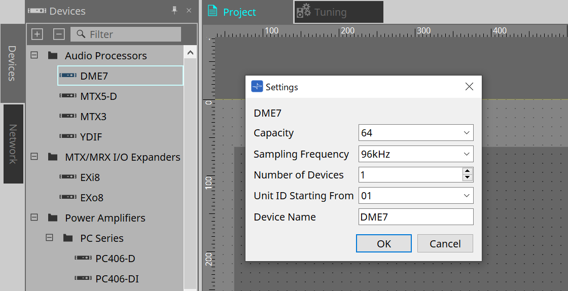
You can place devices in this sheet. The following “Settings” dialog box appears when you try to place a device.
-
Capacity(DME7 only)
The number of inputs and outputs for the Dante, Matrix Mixer, and Router components. Select from 64, 128, 192, and 256.Match the capacity to that of the DME7 main unit. For more information, refer to the Properties area > Capacity. -
Sampling Frequency
Specifies the sampling rate for the device. Select from 44.1kHz, 48kHz, 88.2kHz, and 96kHz. -
Number of Devices
Selects the number of DME units to be placed in the “Device” sheet. -
Unit ID Starting From
Specifies the device Unit ID number to start with. -
Device Name
Enables you to view and edit the device name.
13.2.1. Tool bar
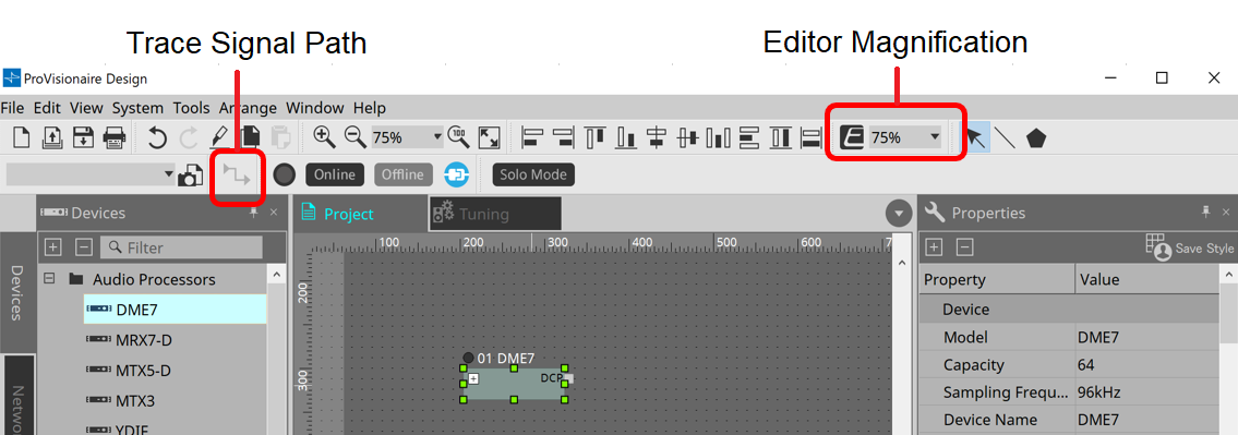
-
Editor Magnification
Enables you to modify the magnification ratio for the component editor. -
Trace Signal Path
If you select a port or wire while this command is turned on, the signal path will be traced starting with the selected point as the origin and display flashing lines connecting to the input and output.
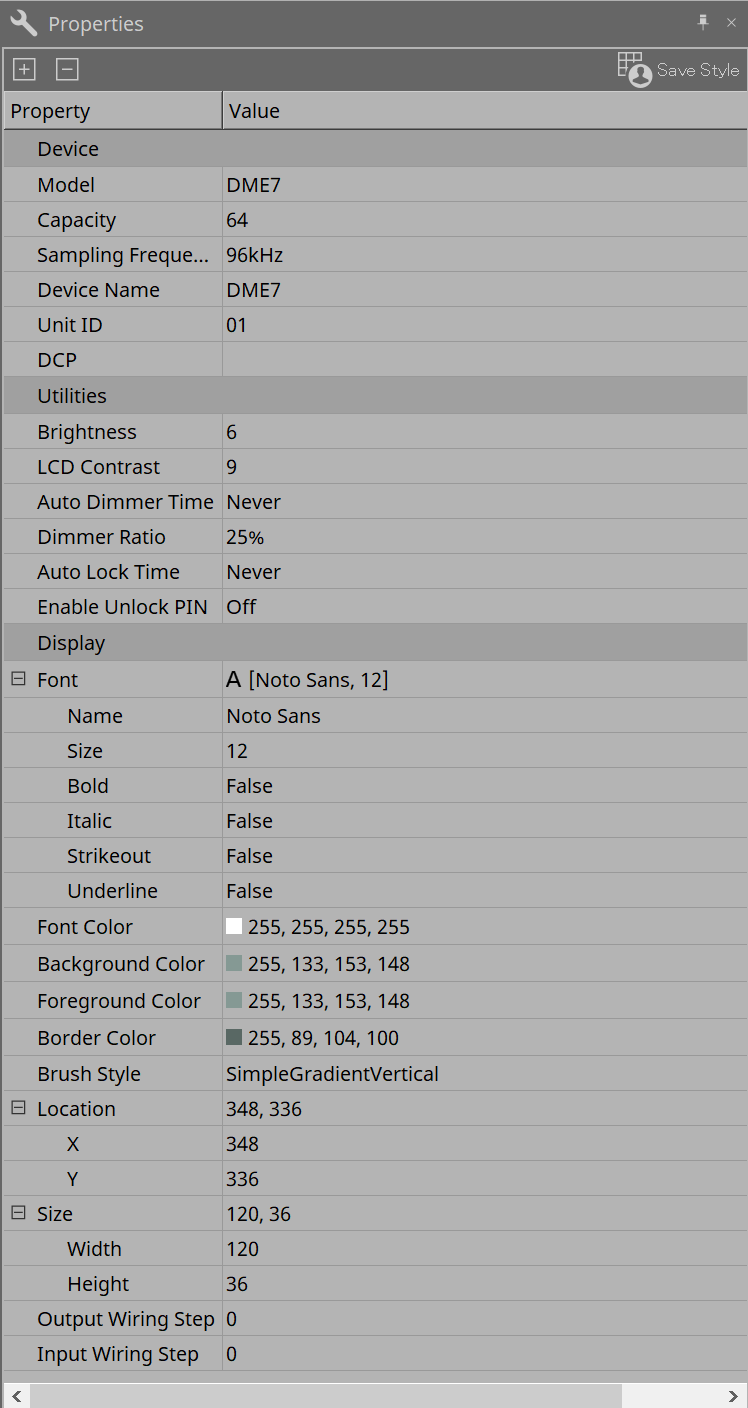
13.2.2. "Properties" area
This area enables you to view and edit the information on the DME.
-
Device
-
Capacity(DME7 only)
The number of inputs and outputs for the Dante, Matrix Mixer, and Router components. Select from 64, 128, 192, and 256.
This capacity must match that of the DME7 unit.
The factory default setting for the capacity of the DME unit is 64. If the capacity is 64, the maximum number of available inputs and outputs for Dante, and for Matrix Mixer and Router components, is 64-in/64-out.
Each time you add a license (DEK-DME7-DX64), the number of inputs and outputs for Dante, and for Matrix Mixer and Router components, will increase by 64 channels.
You can add up to three licenses. Refer to the “Device License Activation Guide” for more information on how to add a license to the device. -
Sampling Frequency
Specifies the sampling rate for the device. Select from 44.1kHz, 48kHz, 88.2kHz, and 96kHz.
This rate must match the sampling rate for Dante. -
Unit ID
This value must match the Unit ID for the DME unit. The factory default setting is 1. -
DCP
Select a DCP (Digital Control Panel) to connect to the DCP port on the DME.
If you select a DCP, the DCP component will be added to the “Device” sheet.
-
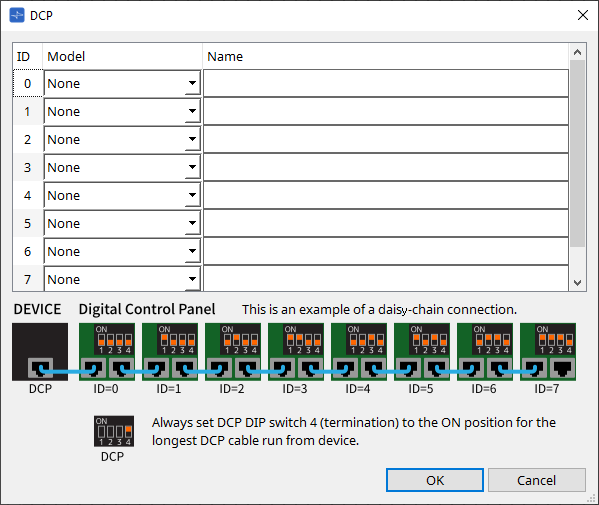
Refer to the
DCP
section for details.
For the rest of the items, refer to the description that appears when the corresponding items are selected in the “Properties” area.
13.3. Device sheet screen configuration
Device sheet consists of a menu bar, tool buttons, “Components” area, “Parameter Sets” area, design sheet, “Properties” area, “Parameters” area, and “Bird’s Eye” view.
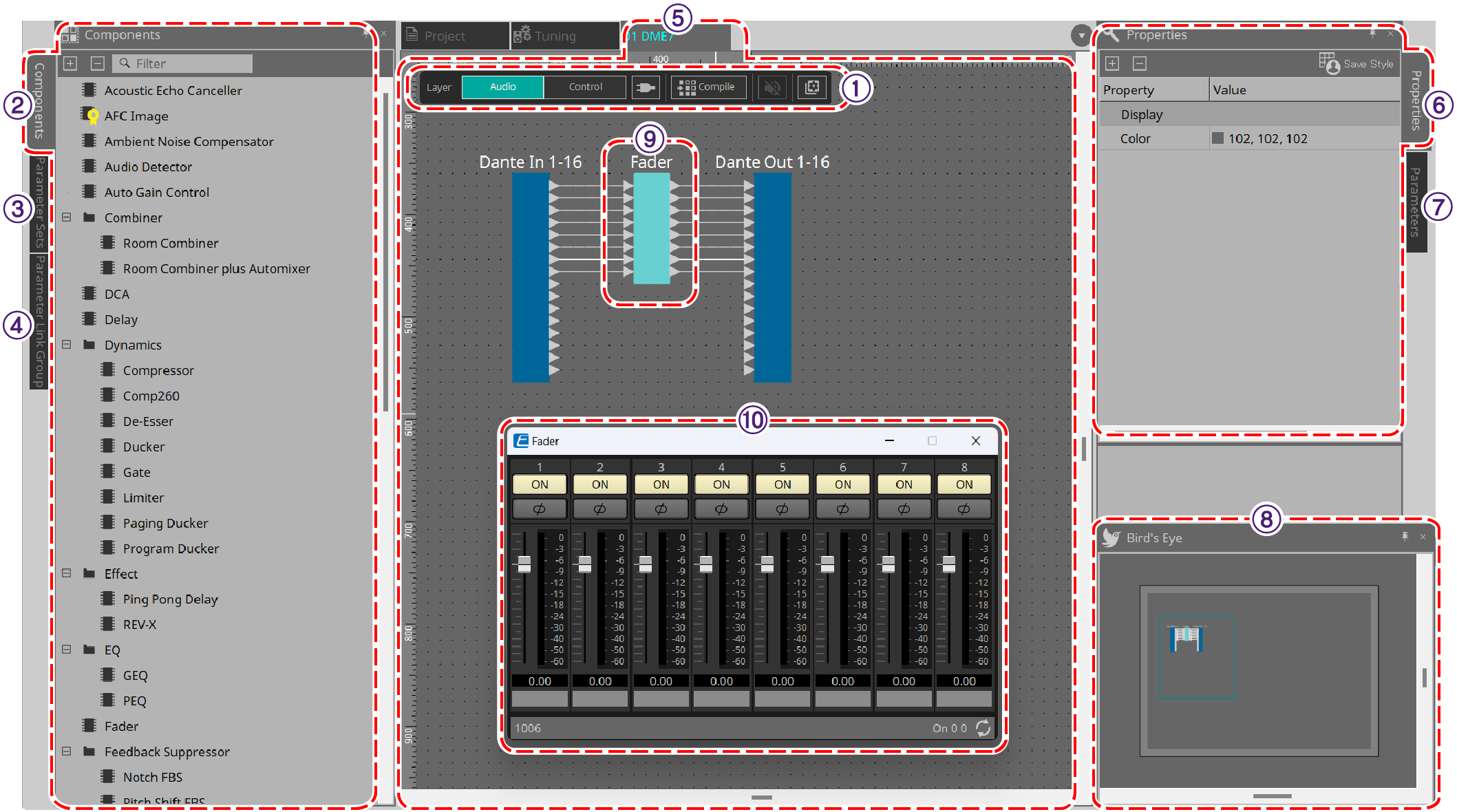
①
Tool buttons
Frequently-used commands are provided here as buttons
(Tool buttons)
.
②
“Components” area
Lists components for the Audio layer and Control layer respectively
(“Components” area)
.
③
“Parameter Sets” area
Enable you to configure parameter sets or snapshots
(“Parameter Sets” area)
.
④
“Parameter Link Group” area
Enables you to create a parameter link group to link multiple parameters of the Level-type and ON/OFF-type
(“Parameter Link Group”area)
。
⑤
Design sheet
In this sheet you can place and connect components
(Design sheet)
.
⑥
“Properties” area
Enables you to modify the settings for the currently-selected component, port, or wire
(“Properties” area)
.
⑦
“Parameters” area
Lists components that have been placed in the “Design” sheet (Audio layer or Control layer), and their parameters
(“Parameters” area)
.
⑧
"Bird’s Eye" view
This shows an overview of the sheet.
⑨
Component
Various signal processing modules, such as an equalizer or compressor, are called “components.”
⑩
Component editor
Use the component editor to specify the parameters.
13.4. Basic use of ProVisonaire Design
-
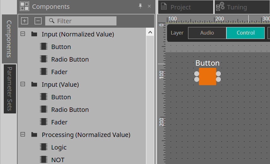
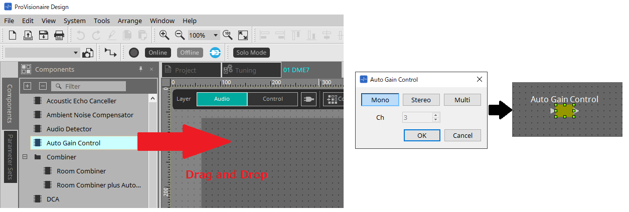
From the “Components” area at the left, drag the component that you want to use and drop it on the design sheet.
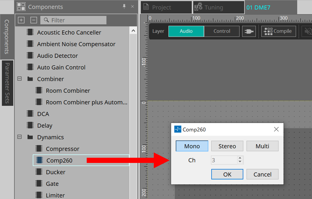
If you drop a component that has multiple candidates such as channels, the candidates are displayed; select the one that you want to use as necessary.
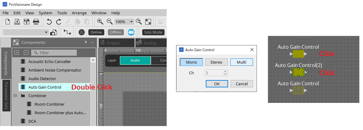
| Double-click on a component in the “Components” area to select Stamp mode; in this mode, components are placed successively each time you click the design sheet. To cancel Stamp mode, press < Esc > or click any component in the list. |
-
To make a connection, drag the
 of a component and drop it on the
of another component.
of a component and drop it on the
of another component.
For details, refer to Connecting ports .
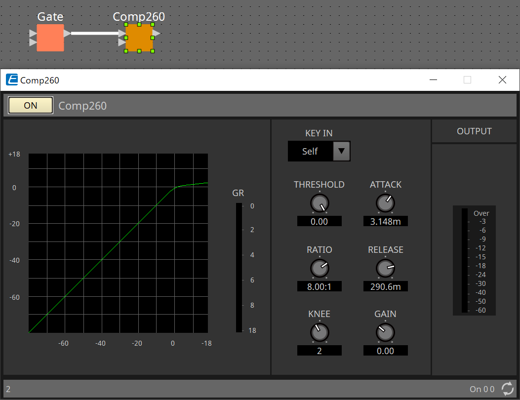
-
Double-click a component or right-click it and choose “Open Component Editor”; the component editor opens, allowing you to operate the parameters.
-
When you have made the necessary settings, click the “Compile” button to check whether there are any problems with the placement and connections of the component.

13.5. Tool buttons
Commands frequently used in DME are provided as buttons.
| Button | Command | Summary |
|---|---|---|
|
|
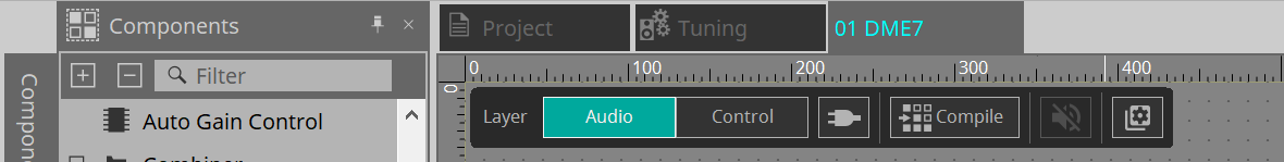
[Layer] |
Switch between the Audio layer and Control layer.
|
|
|
[Control Function] |
Turn this button on to emulate the configuration in the Control layer. While the button is turned on, you cannot modify the configuration. |
|
|
[Compile] |
Analyzes whether there is any problem with the component placement and wiring. |
|
|
[Device Mute] |
Mutes the DME7. |
|
|
[Tools] |
[Remote Control Setup List]
|
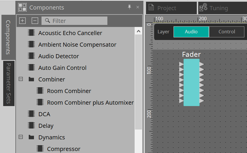
13.6. "Components" area
Components are available for the Audio layer and Control layer respectively.
For details on components, refer to the "ProVisionaire Design Component Guide" .
13.7. Design sheet
Here you can place components and connect them.
Parameter settings are the main operations that you can perform while online. Operations such as placing and connecting components can only be done while offline.
13.7.1. Placing components
Here we explain how to place components on the design sheet.
| If any component in the “Components” area is selected, pressing an alphabetical key will select the component of the matching initial letter. |
-
Placing a single component
Drag a component from the list in the “Components” area and drop it on the design sheet.
-
Placing multiple instances of the same component
Double-click on a component in the “Components” area to select Stamp mode; in this mode, the component is placed each time you click the design sheet. To cancel Stamp mode, press < Esc > or click any component in the list.
-
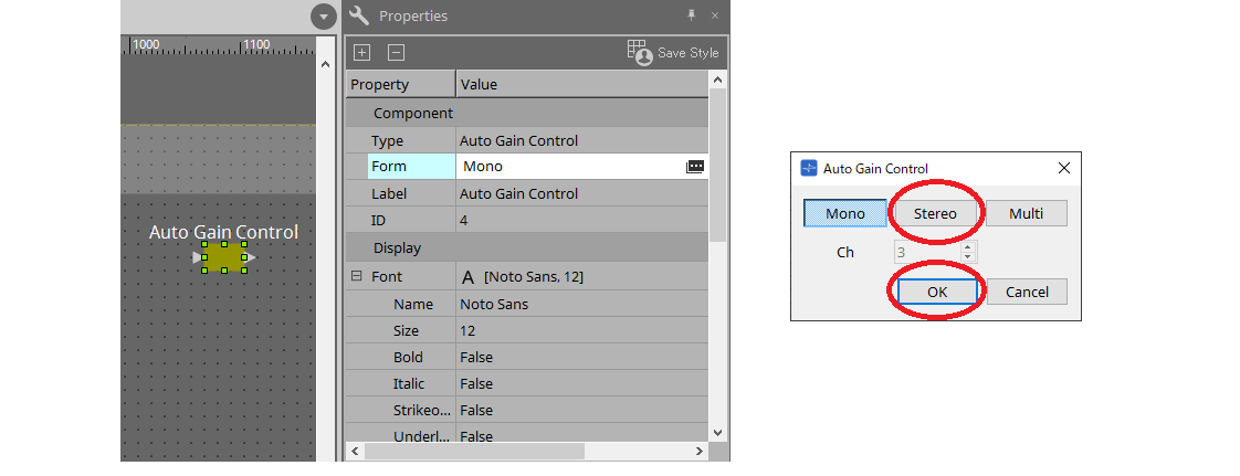
Changing the number of channels for a component you placed
In the “Properties” area, click the property Form field; then click the […] that appears and select the desired number of channels. This cannot be changed on a component for which […] is not shown.
13.7.2. Selecting multiple components, ports, or wires
Here’s how to select multiple components placed in the design sheet, or multiple wires that connect ports of components.
-
Use the mouse cursor to completely enclose objects
Drag the mouse cursor to select the components, component ports, wires, and text that are completely enclosed by the rectangular area in the design sheet.
|
If the selection encloses an expanded User Defined Block, and the point at which you start dragging is on the style sheet, then the objects on the style sheet are selected. If
the point at which you start dragging is on a User Defined Block, then objects on the User Defined Block are selected. |
-
Hold down < Ctrl > and use the mouse cursor to completely or partially enclose objects
Hold down < Ctrl > and drag the mouse cursor to select the components, component ports, wires, and text that are completely or partially enclosed by the rectangular area in the design sheet.
| If the selection encloses an expanded User Defined Block, and the point at which you start dragging is on the style sheet, then the objects on the style sheet and the User Defined Block are selected. If the point at which you start dragging is on a User Defined Block, then objects on the User Defined Block are selected. |
-
Hold down < Ctrl > and click objects
Hold down < Ctrl > and click the target that you want to select.
If you hold down < Ctrl > and click an object that is already selected, the selection is cleared. This is convenient when you have selected multiple objects by enclosing them, and then want to de-select one of the selected objects.
| If objects in a User Defined Block and on the style sheet are simultaneously selected, there are some limitations on operation; for example, you can’t move components. |
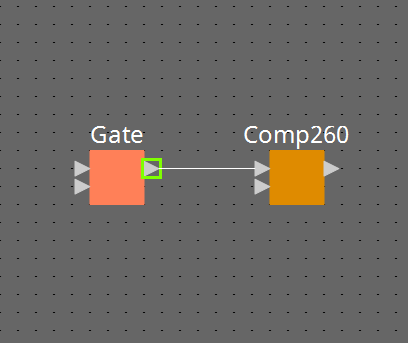
13.7.3. Connecting ports
Here we explain how to make connections between ports of components by creating a wire between the ports.
-
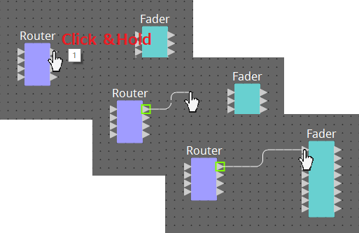
Making one connection at a time
Drag one output port to the input port of the destination component.
-
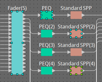
Making multiple connections at a time
Select multiple output ports, and drag one of these ports to an input port of the destination component.
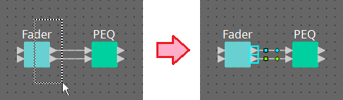
13.7.4. Tracing the signal path
Here we explain how to view the signal path.
To view the signal path, click the
![]() Trace Signal Path button on the toolbar or add a check mark to the [Tools] menu → [Trace Signal Path] command.
Trace Signal Path button on the toolbar or add a check mark to the [Tools] menu → [Trace Signal Path] command.
-
Click a wire
The path of the signal flowing through that wire is shown. -
Click a port
The path of the signal flowing through that port is shown.
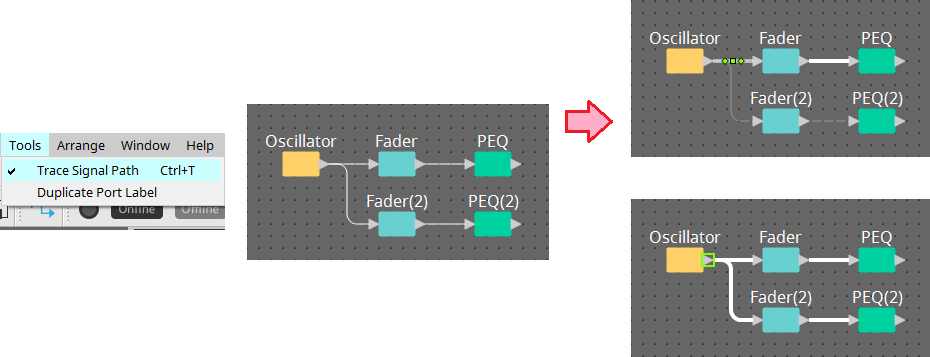
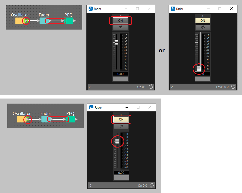
If the signal path is connected but no audio signal flows because it is turned OFF or the level is minimized, the signal path is shown as a dashed line.
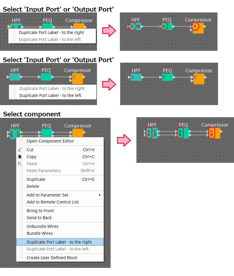
13.7.5. Duplicating an input port name
If you want to use the signal name as the port name, it is convenient to duplicate the port name.
Here we explain how to automatically duplicate the input port name.
In general, the input port name is automatically duplicated to the input port of the connection destination component, but the following exceptions apply.
-
For a mixer-type component or a component that has only an output, the output port name is duplicated to the input port of the connection-destination.
-
If the duplication-source port name is blank, it is not automatically duplicated.
| If the port name has already been specified, the port name is overwritten by the automatic duplication. |
-
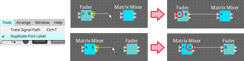
Automatically duplicating the port name when components are connected
If [Tools] menu → [Duplicate Port Label] has a check mark, the port name is automatically duplicated when you make a connection between components.
-
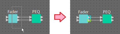
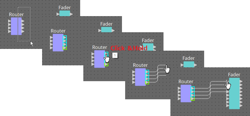
Duplicating the port name of components along the signal path
In the context menu that appears when you right-click a port or component, choose [Duplicate Port Label - to the right] or [Duplicate Port Label - to the left]; the input port name is duplicated to the input port of the following or preceding components.
However if a mixer-type component exists within this path, duplication stops at the mixer-type component.
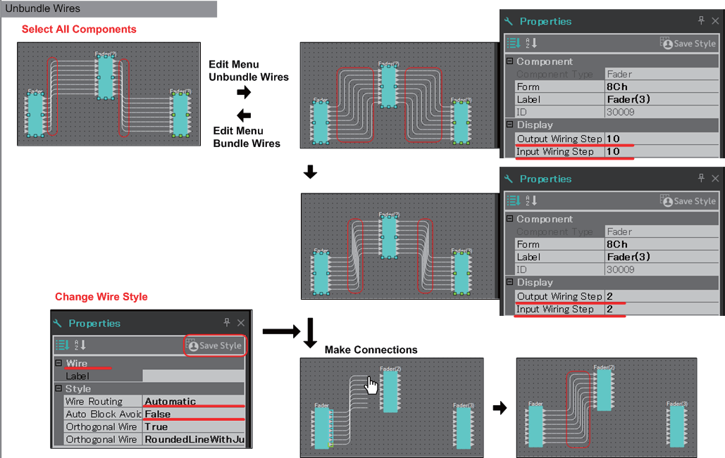
13.7.6. About [Unbundle Wires]
After you have placed all of the necessary components and have finished creating wires between them, you can select all components and execute [Unbundle Wires] to prevent the wires from overlapping in the display.
When you execute [Unbundle Wires], the items in the “Properties” area for the components and the wires connected to the components are set to the following values.
| Item | Value | |
|---|---|---|
|
Component |
Output Wiring Step |
An appropriate value will automatically be displayed. |
|
Input Wiring Step |
An appropriate value will automatically be displayed. |
|
|
Wire |
Wire Routing |
Automatic |
|
Auto Block Avoidance |
False |
If you want to selectively change the spacing between the wires, perform the operation above, and then change the [Output Wiring Step] or [Input Wiring Step] values.
If you don’t want wires to overlap when you’re making connections, execute the following procedure.
-
Place all components.
-
Select all components, and execute [Unbundle Wires].
-
Make one connection between components, and select the wire.
-
Set the wire’s [Wire Routing] to [Automatic], and set [Auto Block Avoidance] to [False].
-
Click the [Save Style] button to save the wire’s user style to the computer.
Subsequently when you connect wires, they are shown without overlapping.
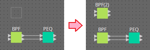
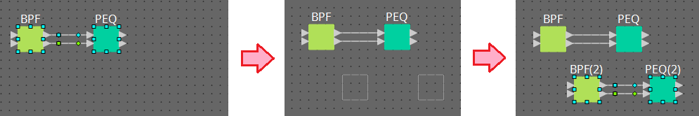
13.7.7. Duplicating components
Here we explain how to duplicate components together with their parameters.
-
Right-click a component and choose [Duplicate]
A duplicate, overlapping component is created. If multiple components with their wires are selected when you choose [Duplicate], the components are duplicated together with their wires.
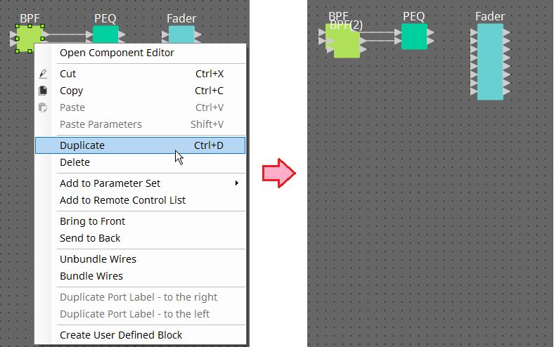
-
Drag and drop a component while holding down < Ctrl >
A duplicate is created where you drop the component.
-
Drag and drop multiple components with their wires while holding down < Ctrl >
Duplicates of the components together with their wires are created where you drop the component.
13.8. Design sheet: Audio layer
This layer enables you to place audio components to create a configuration.
You can control audio signals by wiring between audio components.
13.8.1. Audio Component
For more information on how to use the component editor, refer to Chapter 12.
For details on components, refer to the
"ProVisionaire Design Component Guide"
.
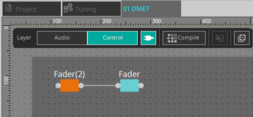
13.9. Design sheet: Control layer
This layer handles control signals.
You can manipulate control signals by wiring between the control components or audio components.
Control components can be manipulated via changes in parameters or meters for the audio components. Audio components can be manipulated via changes in parameters for the control components.
You can also place snapshots in the Control layer, which can be treated as part of the configuration.
Control Component
For more information on how to use the component editor, refer to Chapter 12.
For details on components, refer to the
"ProVisionaire Design Component Guide"
.
13.9.1. Using the audio component parameters in the Control layer
-
Select the Audio layer.
-
Select the “Parameters” area, and then select the audio component in the sheet.
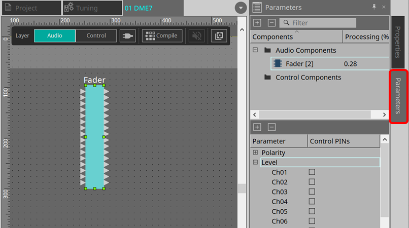
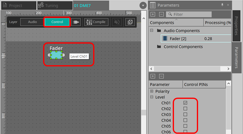
In the Control PINs column, add a check mark to the check box for the desired parameters. The audio component is placed in the Control layer, too.
If you turn off the “Layer Link” command (one of the Tools buttons), the position of the audio component placement will be asynchronized (unlinked) between the Audio layer and Control layer.
-
Place the control component in the Control layer and do the necessary wiring.
-
Turn on the [Control Function] button
 and manipulate the control component parameters to simulate the operation.
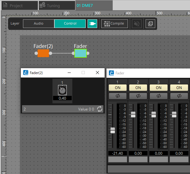
| You cannot edit the configuration while the [Control Function] button is turned on. |
13.9.2. Controlling a Snapshot and ParamSet in the control component
You can control a snapshot and parameter set in the control component.
For more information on the parameter set and snapshot, refer to the “’Parameter Sets’ area” section.
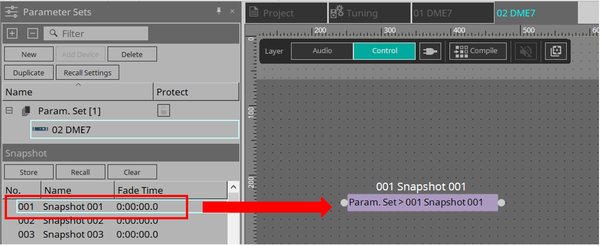
■ An example of control using the Snapshot component
-
Drag and drop a snapshot from “Snapshot” in the “Parameter Set” area to the Control layer. The Snapshot component appears in the Control layer.
-
Snapshot is recalled when a signal is input to the input port.
-
When the snapshot is recalled, “1” is output from the output port.
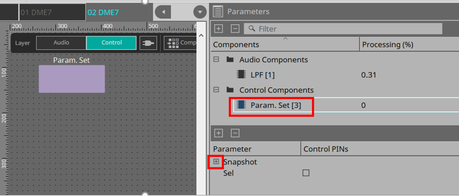
■ An example of control using the ParamSet component
You can also control a snapshot using the ParamSet component. In this section, two control examples are introduced: using Snaspshot pins, and using a Sel pin.
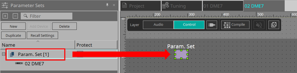
[1] An example of control using Snapshot pins
-
Drag and drop the Parameter Set in the “Parameter Sets” area to the Control layer. The Param.Set component that includes multiple Snapshot components appears in the Control layer.
-
Select Parameter Set in the “Parameters” area, and then click the “+” mark next to “Snapshot” to expand the snapshot list.
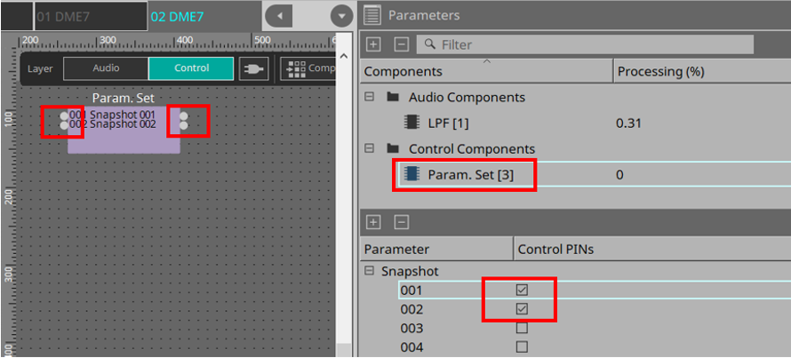
-
Add a check mark to the check box for a desired Snapshot number in the Control PINs column. Input/output ports are added to the components on the sheet. The recall method is the same as the "■ An example of control using the Snapshot component".
[2] An example of control using a Sel pin
-
Select Parameter.Set in the “Parameters” area, and then add a check mark to "Sel" in the Control PINs check box, it will be added to the input port of the component on the sheet.
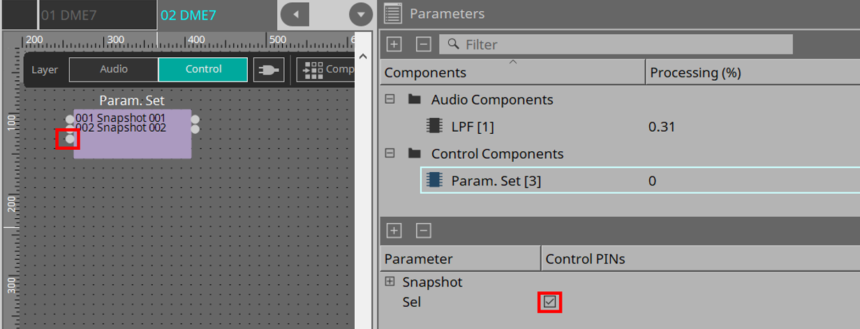
-
Enter a desired number (1 to 100) into the Sel input pin. The Snapshot component corresponding to that number is recalled. (At this time, the output pin for this component outputs “1.”)
13.10. Components other than audio or control components
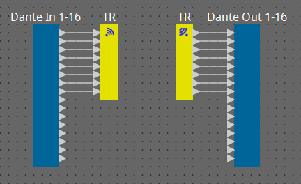
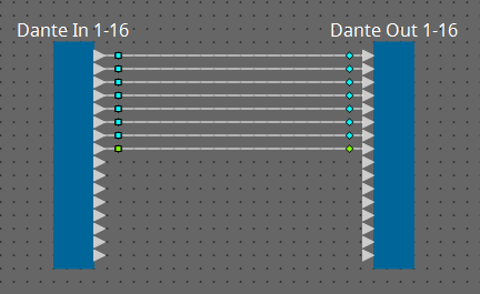
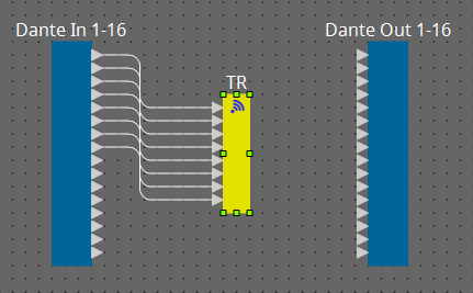
13.10.1. Transmitter/Receiver
This function wirelessly connects components that are located at a distance from each other on the design sheet.
The Transmitter component and Receiver component of the same component label are connected.
If there are multiple ports, identically-numbered ports are connected to each other. One Transmitter component can be connected to multiple Receiver components.
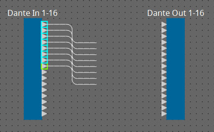
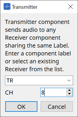
When placing this component in the design sheet, select the component label and the number of channels. Either enter a new name as the component label, or select a component label with which it will be associated. As the number of channels, select the number of channels that you want to use.
When you select a wire and press < Space >, a Transmitter component and Receiver component are added.
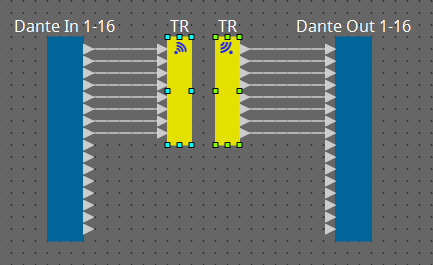
If you hold down the mouse button in the middle of a connection and press < Space >, a Transmitter component or Receiver component is created.
13.10.2. User Defined Block
Components and the wires between components can be encapsulated as a User Defined Block. By encapsulating multiple components as a single block, you can make the style sheet look cleaner, or copy blocks to easily create the same functionality for other channels.
A protect function is provided for User Defined Block. By protecting it, you can prevent another person from changing the configuration or parameters, or prevent them from looking inside.
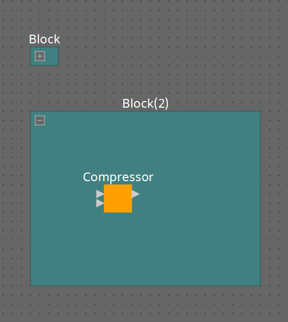
Here’s how to place a User Defined Block.
-
Drag and drop from the “Component” area. (An empty block is placed.)
-
With the components selected, right-click and choose [Create User Defined Block]. (This places a block that contains the selected components.)
-
With the components selected, choose [Edit] menu → [Create User Defined Block]. (This places a block that contains the selected components.)
When placing a User Defined Block, specify the number of inputs and outputs as a block. The number of inputs and outputs can be changed later in “Form” of the “Properties” area. The inputs and outputs directly connect components outside the block with components inside the block.
To show or hide the contents of a block, click the [+]/[–] in the upper left of the block, or doubleclick the block.
Components in a block can be placed, connected, and edited in the same way as in a design sheet.
With a block selected, you can drag and drop the top, bottom, left, or right corners to expand or shrink the block. With an expanded block selected, you can drag and drop the top, bottom, left, or right edges to move the block on the design sheet.
Here’s how to unpack a User Defined Block.
-
Right-click the block and choose [Unpack User Defined Block].
-
With the block selected, choose [Edit] menu → [Unpack User Defined Block].
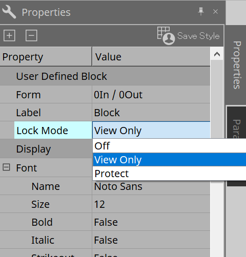
There are three User Defined Block protection modes.
-
Off mode
The unprotected state. -
View Only mode
A protected User Defined Block or a component editor inside the block can be opened, but the configuration and parameters cannot be changed. Components in the User Defined Block are not shown in the “Parameters” area.
A lock icon ( ) is shown at the lower left of the component editor in a protected block.
-
Protect mode
A protected User Defined Block cannot be opened. Components in the User Defined Block are not shown in the “Parameters” area. Use this when you want to keep the content completely concealed.
A lock icon ( ) is shown at the upper left of the protected block.
To apply protection, proceed as follows.
-
Select the User Defined Block that you want to protect.
If you select multiple User Defined Blocks, they will be protected in the same mode. -
In the “Properties” area, use [Lock Mode] to specify the lock mode that you want to apply.
-
As necessary, repeat steps 1 and 2 to specify the lock mode for other User Defined Blocks.
-
Choose [Edit] menu → [Protect User Defined Block] from the [Tools] button in the “Device” sheet.
The “Protect User Defined Block” dialog box appears.
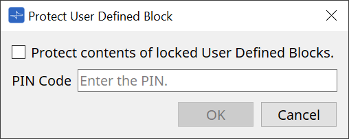
Enter the PIN code and click the OK button to set the same PIN to all User Defined Blocks whose Lock Mode is "Protect".
To remove protection, proceed as follows.
-
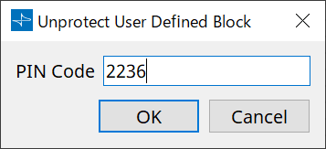
Choose [Edit] menu → [Protect User Defined Block] from the [Tools] button in the “Device” sheet.
The “Unprotect User Defined Block” dialog box appears.
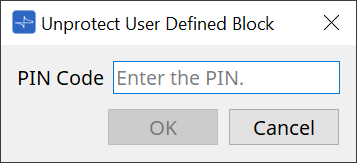
-
Enter the PIN Code that was specified when locking, and click the [OK] button.
The “Protect User Defined Block” dialog box appears.
-
Clear the check mark from the “Protect contents of locked User Defined Blocks” check box.
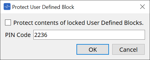
-
Click the [OK] button.
Protection is removed. The [Lock Mode] setting is maintained.
13.10.3. Text
This is a text box used to place text in the design sheet.
You can double-click the area displayed as [Text], and enter text.
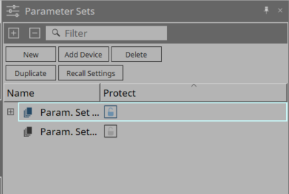
13.11. “Parameter Sets” area
A set of parameters stored or recalled as a snapshot is called a “parameter set.” Storing a snapshot saves the current values of the parameter set members. One parameter set can store up to 100 different snapshots. A parameter can be registered in more than one parameter set.
Parameters can be registered in a parameter set in the following ways.
| Registration source | Registration method |
|---|---|
|
Design sheet |
While holding down < Ctrl >, drag and drop a component onto a parameter set name. |
|
Right-click a component, and use [Add to Parameter Set] to select the parameter set to which it will be registered. |
|
|
Component editor |
While holding down < Ctrl >, drag and drop a parameter onto a parameter set name. |
|
“Parameters” area*1 |
Drag and drop the component or parameter onto a parameter set name. |
|
Right-click the component or parameter, and use [Add to Parameter Set] to select the parameter set to which it will be registered. |
|
|
“Parameter Sets” area |
After selecting the parameter set to register, click the [Add Device] button to register all components placed at that point. |
*1. You can also use < Shift > or < Ctrl > to simultaneously register multiple components or parameters in a parameter set.
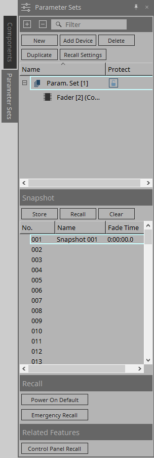
13.11.1. Parameter Sets
-
[New] button
Creates a new parameter set. -
[Add Device] button
Registers an individual device to the parameter set. -
[Delete] button
Deletes the selected parameter set, DME, component, or parameter.
| If you changed the members that were registered to a parameter set, you must overwrite and save the snapshots again. |
-
[Duplicate] button
Duplicates the selected parameter set. If you want to duplicate the snapshots as well, add a check mark to [Duplicate Snapshots Also] in the “Duplicate” dialog box that appears. -
[Recall Settings] button
To start or stop file playback via the GPI Out or SD card along with the snapshots, use the “Recall Settings” dialog box to set up. -
Parameter set name
Shows the name of the parameter set. You can double-click the parameter set name and edit it.
|
A number displayed next to the parameter set name is the parameter set ID. You can specify this ID when you recall a snapshot via the remote protocol command.
To modify the ID, right-click the parameter set name to display the context menu, and then select [Change ID]. |
| If any parameter set in the “Parameter Sets” area is selected, pressing an alphabetical key will select the parameter set of the matching initial letter. |
-
Protect
If Protect is turned on, you will be unable to change the parameter set or store snapshots.
Click here repeatedly to turn Protect on ( ) or off (
 ).
).
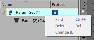
Right-click the parameter set name to open the context menu .
13.11.2. Snapshot
-
[Store] button
Stores (saves) a snapshot. -
[Recall] button
Recalls a snapshot. -
[Clear] button
Deletes a snapshot. -
[Fade Time] field
This shows the time (Fade Time) that is taken to change the level of fader components or the send level of Matrix components that are registered in the parameter set. Doubleclick this to open the “Fade Time” dialog box. In the dialog box that appears, specify the time over which the change will happen. You can specify up to three hours. -
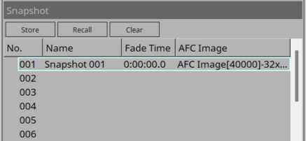
[AFC Image]field
This shows the AFC Image components and scene numbers specified in the "Select AFC Image Scene" dialog box. When you recall a snapshot, the scene of the specified AFC Image component will also be recalled.AFC Image components cannot be registered in a Parameter Set. Double-click the [AFC Image] field to open the "Select AFC Image Scene" dialog box.
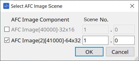
-
AFC Component
AFC Image components already placed will be displayed.
If the checkbox is selected, the scene of the AFC Image component will be recalled at the same time as the snapshot. -
Scene No.
Specify the scene number of the AFC Image component to be recalled.
-
|
To create a scene of an AFC Image component, use the AFC Image Controller.
For details about AFC Image components and the AFC Image Controller, refer to the AFC Image Controller User Guide. |
13.11.3. Recall
-
Power On Default
You can specify whether a snapshot will be recalled when you turn on the power to the unit. Press the [Set] button in the “Power On Default” dialog box if you want the currently-selected snapshot to be recalled.
If the snapshot is not assigned to be recalled, the unit will start up using the latest setting obtained immediately before the power was turned off. To cancel the assignment, select [Clear] in the “Power on Default” dialog.

-
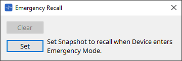
Emergency Recall
You can specify whether a snapshot will be recalled if the DME receives an EMG (Emergency) signal from an external device, or if the input voltage to the [GPI IN] connector (IN 16) (which supports +24V) falls below 2.5V.
Refer to the “Power On Default” dialog box section for information on how to set or clear the assignment.
13.11.4. Related Features
-
Control Panel Recall
Register the snapshot that will be recalled on the device control panel.
Click the button to register it.
Click the button to delete a snapshot from the registration list.
Click the button to delete all snapshots from the registration list.
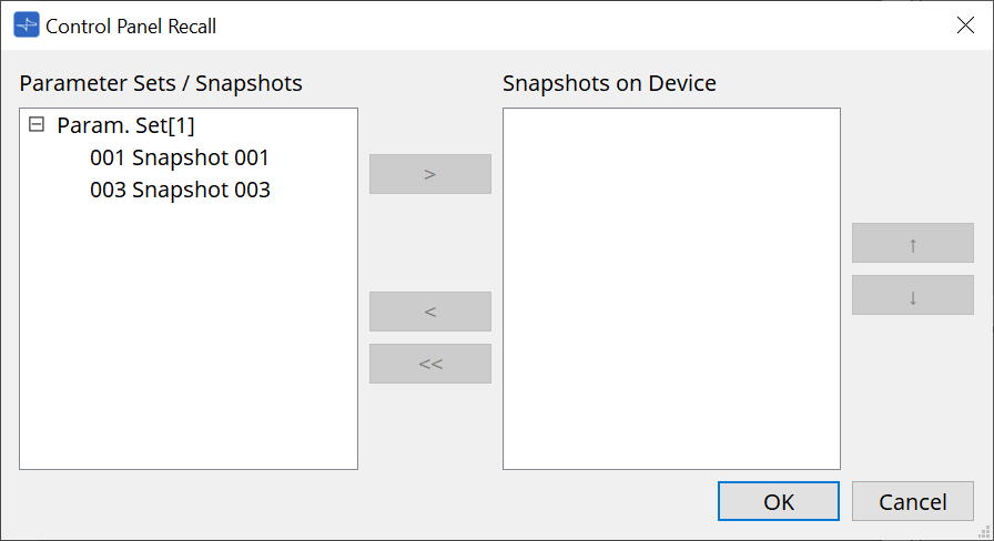
Use the up and down arrow buttons to change the order of the snapshots displayed on the device panel.
13.11.5. "Recall Settings" dialog box
-
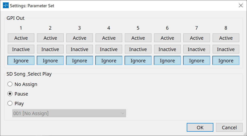
GPI Out
Here you can specify the GPI OUT settings that will be output when the snapshot is recalled.
You can use GPI OUT output to control a device that’s connected to this unit’s [GPI OUT] connector.
[Active]/[Inactive]/[Ignore] buttons
Specify whether the GPI OUT connector’s output will be enabled (Active), enabled with the OUTPUT TYPE inverted (Inactive), or ignored (Ignore).
If the [OUTPUT TYPE] in the GPI Output dialog box setting is set to [Pulse] or [Pulse Inv.], the only available choices will be [Active] and [Ignore].-
If [Active] is specified
When [OUTPUT TYPE] is [Closed], the [GPI OUT] pin will be closed (connected to ground).
When [OUTPUT TYPE] is [Open], the [GPI OUT] pin will be open.
When [OUTPUT TYPE] is [Pulse], the [GPI OUT] pin will be closed (connected to ground) for approximately 250 ms.
When [OUTPUT TYPE] is [Pulse Inv.], the [GPI OUT] pin will be open for approximately 250 ms. -
If [Inactive] is specified
When [OUTPUT TYPE] is [ Closed], the [GPI OUT] pin will be open.
When [OUTPUT TYPE] is [ Open], the [GPI OUT] pin will be closed (connected to ground). -
If [Ignore] is specified
There will be no change in the output. Use this setting if a different function is assigned to GPI OUT and you don’t want that function to be affected by snapshot recall.
-
-
SD Song Play
-
Pause
Stops playing the file immediately when a snapshot is recalled. -
Play
Plays the specified file immediately when a snapshot is recalled.
You can play files that are stored on the SD card specified in the “SD Card File Manager” dialog box.
-
13.12. Parameter Link Group Area
Creates a parameter link group to link multiple parameters for Level-type or for ON/OFF-type.
A single parameter can be registered in multiple parameter link groups. The created parameter link group can be used in Snapshot, Scheduler, GPI, DCP, MCP1, or the Remote Control Setup List. Level-type and ON/OFF-type cannot be mixed in a single parameter link group. Up to 64 parameter link groups can be created.
The following methods are available for registering to a parameter link group.
[Parameter]
| Registration Source | Registration Method |
|---|---|
|
Component Editor |
While holding the |
|
Right-click the parameter and select the parameter link group to register in [Add to Parameter Link Group]. |
|
|
Parameters Area*1 |
Drag & drop the parameter into the parameter link group in the Parameter Link Group area. |
|
Right-click the parameter and select the parameter link group to register in [Add to Parameter Link Group]. |
*1. Multiple parameters can be registered to a parameter link group simultaneously by pressing < Shift > and < Ctrl > together.
| Pressing any letter key while selecting a parameter link group or other item in the Parameter Link Group area will select the parameter link group or other item with the matching first letter. |
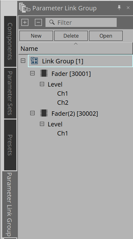
-
[New] Button
Creates a parameter link group. -
[Delete] Button
Deletes the selected parameter link group or parameter. -
[Open] Button
Displays the Link Control editor for the selected parameter link group.
13.12.1. Link Control Editor
There is a link control for each parameter link group. When a link control is changed, the parameters registered in the parameter link group are also changed at the same time.
Even if the parameters registered in the parameter link group are changed, the link control parameters do not change.
Link control can be assigned to GPI/DCP/Remote Control Setup List/Parameter Link Group/MCP1.
The name of the parameter link group is displayed in the title bar.
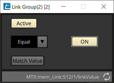
| Level-type | ON/OFF-type |
|---|---|
|
|
|
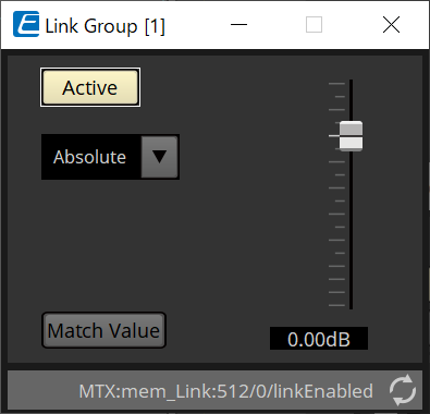
-
Fader (level-type only)
Sets values for level-type parameters. -
[ON] Button (ON/OFF-type only)
Sets values for on/off-type parameters. -
[Match Values] Button
If [Absolute] or [Equal] is selected in the combo box, the value of the registered parameter will be the same as the value of the link control. -
[Active] Button
If this is on, the parameter link group is enabled. Turn this off if you want to temporarily disable the link. -
Combo Box
Set how the level-type and ON/OFF-type settings are applied.
|
[Absolute]/[Equal] |
Sets the value of the registered parameter to the same value as the link control. |
|
[Relative]/[Opposite] |
When you operate the link control, the registered parameters will move while maintaining their relative positions. |
13.13. Temporary Link Group
This group allows you to temporarily use the same functionality as Parameter Link Group without creating it.
Use this group when you want to temporarily link parameters without creating a Parameter Link Group.
Procedure
-
While holding down the < Ctrl > and < Shift > keys, click a parameter in the component editor to select it. The selected parameter will be framed in green.
When you click the first parameter, the Temporary Link Group editor will be displayed.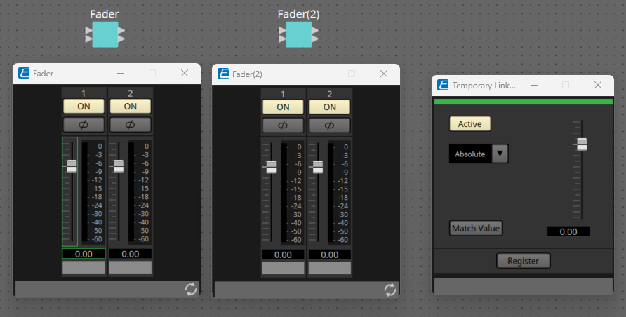
-
While holding down the
and keys, click another parameter to select it.
You can also select parameters across multiple component editors.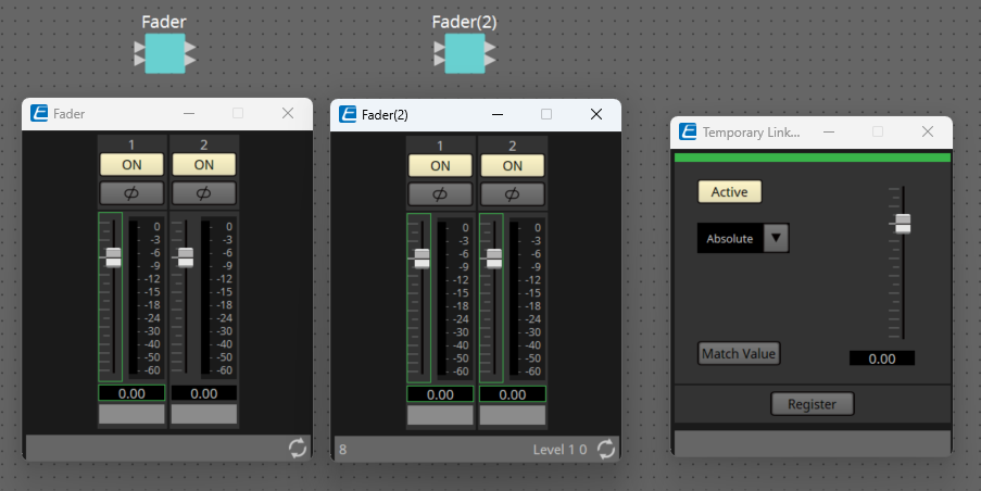
-
The Temporary Link Group editor allows you to perform link operations similar to those for the Parameter Link Group.
-
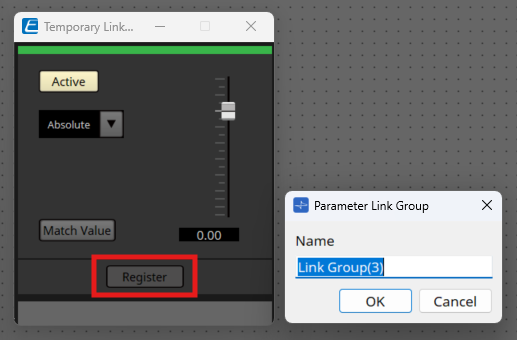
You can also click the Register button to officially register the selected parameter to the Parameter Link Group.
-
When the Temporary Link Group editor is closed, the parameters will be deselected and the link state will be terminated.
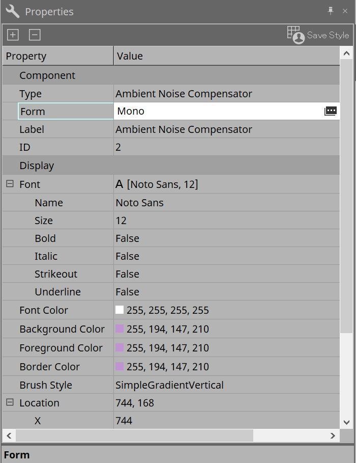
13.14. “Properties” area
In this area you can edit setting for the currently-selected component or wire.
-
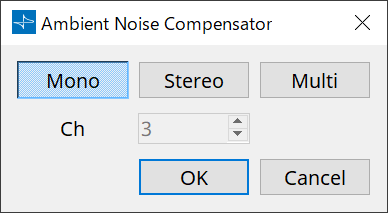
Component
Click the Value field in the "Component"/"Form" to make the appear, a dialog for changing the number of channels of the component, etc. will be displayed.
This cannot be changed on a component for which
is not shown.
-
Port
If you click on the
that appears when you click on the "Label" Value, the
Port Label dialog
box will be displayed, allowing the labels of all ports of the component to be edited at once.
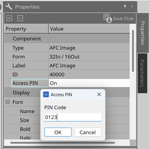
-
Access PIN
This setting item relates to the AFC Image components.
It prevents unexpected setting changes by the AFC Image Controller. After you set a PIN, you will be prompted to enter it when the AFC Image Controller accesses the AFC Image component.When this item is changed from Off to On, the "Access PIN" dialog box will appear, allowing you to set a PIN.
The PIN is a four-digit number in combination of 0 to 9. When this item is set to Off, the PIN is deleted.
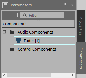
13.15. "Parameters" area
This area displays information about the component that is currently selected in the Design sheet (Audio layer or Control).
The upper part of this area indicates the signal processing capacity of each component as a percentage.
The lower part of this area lists the parameters for the component currently selected in the upper part.
If you add a check mark to the check box in the Control PINs column, you will be able to control the corresponding parameter in the Control layer.
From this area, you can assign components and parameters to a parameter set, Remote Control Setup List, GPI dialog box, MIDI dialog box, and DCP component. For more information on how to assign them, refer to the section for the corresponding dialog box or screen.
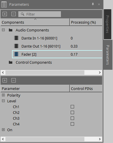
-
Components
Lists the components currently selected in the sheet.-
Processing
Indicates the resources to be processed as a percentage.
-
-
Parameters
Lists the parameters for the component currently selected in the upper part.-
Control PINs
If you add a check mark to the check box in this column, you will be able to control the corresponding parameter in the Control layer.
Immediately after you add a check mark, the corresponding audio component will be placed in the Control layer.
-
13.16. Context Menu
The following describes the contents of the context menus that are displayed when you right-click each area.
13.16.1. Design sheet
The following context menu appears when you right-click a design sheet that contains no objects.
| Menu | Content |
|---|---|
|
[Paste] |
Pastes the copied component in the “Design” sheet. |
|
[Select All] |
Selects all components and wires in the design sheet. |
|
[Close All Editor Windows] |
Closes all component editor and parameter setting windows. |
|
[Snap to Grid] |
If this is checked, objects are aligned with the grid of the design sheet. |
|
[Layer Link] |
Enable this command to synchronize (link) the position of the audio component placement between the Audio layer and Control layer. |
13.16.2. Components
When you right-click a component, the following context menu appears (not all items are shown for all components).
| Menu | Content |
|---|---|
|
[Open Component Editor] |
Opens the component editor. |
|
[Cut] |
Moves the selected item to the copy buffer. |
|
[Copy] |
Copies the component, including the parameter settings of the component editor. |
|
[Paste] |
Paste the copied component onto the design sheet. |
|
[Paste Parameters] |
Duplicates the copied component, including the parameter settings of the component editor. |
|
[Duplicate] |
Duplicates the copied component, including the parameter settings of the component editor. |
|
[Delete] |
Deletes the component. |
|
[Add to Parameter Set] |
Registers the component to the parameter set. |
|
[Add to Remote Control List] |
Registers all of the component’s parameters or the component’s meters in the Remote Control Setup List.
|
|
[Bring to Front] |
Moves the component display to the foreground. |
|
[Send to Back] |
Moves the component display to the background. |
|
[Unbundle Wires] |
Displays the wires connected to the selected component or User Defined Block spaced apart at equal intervals. |
|
[Bundle Wires] |
Displays the wires connected to the selected component or User Defined Block overlaid together. |
|
[Duplicate Port Label - to the right] |
Duplicates the input port name of the selected component to the input ports of the downstream components along the signal path. |
|
[Duplicate Port Label - to the left] |
Duplicates the input port name of the selected component to the input ports of the upstream components along the signal path. |
|
[Create User Defined Block] |
Encapsulates the selected components as a User Defined Block. |
13.16.3. Component Ports
| Menu | Content |
|---|---|
|
[Duplicate Port Label - to the right] |
Duplicates the port name of the input port corresponding to the selected input or output port to the input ports of the downstream components along the signal path. |
|
[Duplicate Port Label - to the left] |
Duplicates the port name of the input port corresponding to the selected input or output port to the input ports of the upstream components along the signal path. |
13.16.4. Component editor / Parameter setting window
When you right-click a component editor or a parameter setting window, the following context menu appears.
| Menu | Content |
|---|---|
|
[Register as default values] |
Register the component’s current parameter values in a style as the default values. New components will be placed with the registered default values.
|
|
[Reset default values to Factory Default] |
Returns the default value of the component to the values immediately after ProVisionaire Design was installed. |
|
[Copy] |
Copies the component, including the parameter settings of the component editor. |
|
[Paste Parameters] |
Content If you select an existing component of the same type and execute this, the copied parameters of the component are applied. |
|
[Add to Parameter Set] |
If you execute this on a parameter, the parameter is registered in the parameter set.
|
|
[Add to Remote Control List] |
If you execute this on a parameter, the parameter is registered in the Remote Control Setup List.
|
13.16.5. Wire
Right-click an item to open the subsequent context menu.
| Menu | Content |
|---|---|
|
[Delete] |
Deletes the wire. |
|
[Bring to Front] |
Moves the selected wire to the front. |
|
[Send to Back] |
Moves the selected wire to the back. |
|
[Add to Transmitter & Receiver Space] |
Connect wires to the Transmitter and Receiver components. |
|
[Insert Node] |
Add nodes to the wire. * A node is a dividing point of a wire. |
|
[Remove Segment] |
Removes wires between nodes. |
13.16.6. “Parameter Sets” area
Right-click an item to open the subsequent context menu.
| Menu | Content |
|---|---|
|
[Find] |
Searches the “Device” sheet for a component or its parameter. |
|
[Delete] |
Deletes the parameter set. Settings in a lower level are also deleted. |
|
[Change ID] |
Enables you to change the parameter set ID. The number displayed next to the parameter set name is the parameter set ID.
|
13.16.7. “Parameters” area
The following context menu appears when you right-click a parameter.
| Menu | Content |
|---|---|
|
[Find] |
If you execute this for a component, the corresponding component in the design sheet is selected.
|
|
[Add to Parameter Set] |
If you execute this on a parameter, the parameter is registered in the parameter set.
|
|
[Add to Remote Control List] |
If you execute this on a parameter, the parameter is registered in the Remote Control Setup List.
|
If you try to add a component to the Remote Control Setup List, the following dialog box will appear.
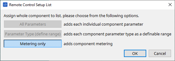
-
[All Parameters] button
Enables you to register all of the component’s parameters. -
[Parameter Type (define range)] button
Enables you to register the component’s parameters by type. -
[Metering only] button
Enables you to register the component’s meters by type.
13.17. Dialog box
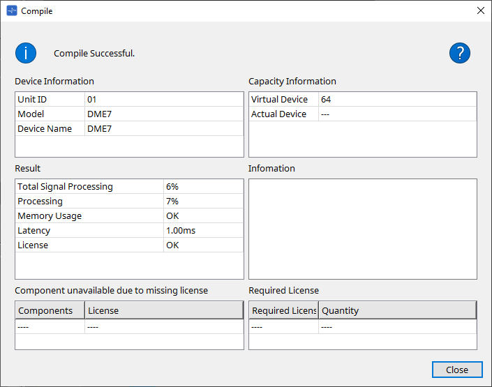
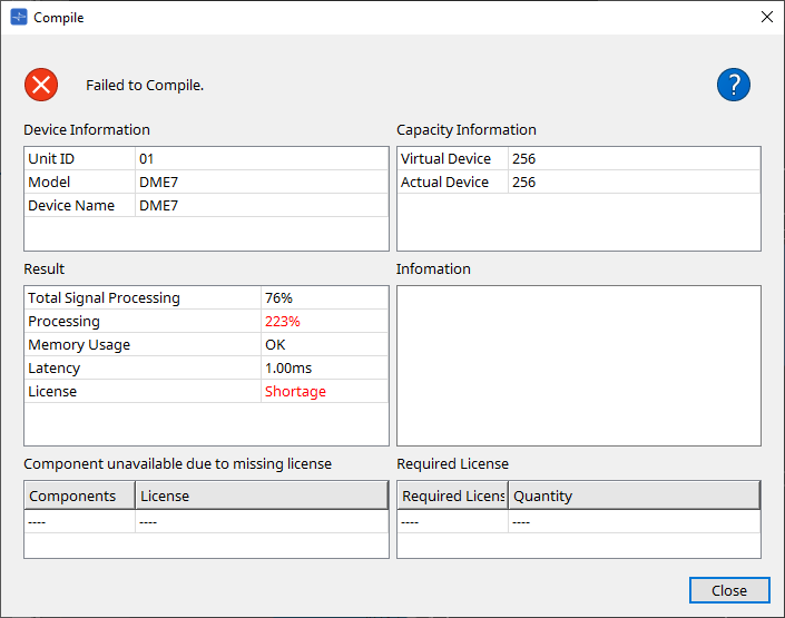
13.17.1. ”Compile” dialog box
To open this dialog box, click the [Compile] tool button in the “Device” sheet.
Analyzes the placement and wiring of the components in the DME system to determine whether there are any problems. Here you can also view statistics such as the resource usage.
-
 /Message
Indicates whether compilation was successful or failed. If it was successful, the message “Compile Successful.” will appear. If it failed, the message “Failed to Compile.” will appear. -
 button
Click here to view the troubleshooting method. -
[Device Information]
This area displays information about the device. -
Device list
-
Unit ID / Model / Device Name
These rows indicate the device Unit ID, device model name, and device name.
To change the device name, use the [Device Name] field in the “Properties” area of the "Project" sheet.
-
-
[Capacity Information]
-
Virtual Device
The number of inputs and outputs for the Matrix Mixer components or others, as set in the Properties area > Capacity of the device. -
Actual Device
The actual capacity of the device discovered by ProVisionaire Design.When this is displayed, compilation will be based on this information.
-
-
[Result]
This area displays the result of compilation. The DME can come online only when compilation is successful.-
Total Signal Processing
Indicates the usage rate of all the signal processing units in the device.
(Supplemental information) The device processes signals using its multiple signal processing units.
The “Total Signal Processing” row indicates the percentage of actual capacity being used (usage rate) based on the aggregated maximum signal processing capacity of all signal processing units as 100%. -
Processing
Indicates the maximum usage rate of each signal processing unit in the device.
The longer the signal path becomes, or the higher the number of inputs and outputs the component features, the higher the usage rate might become. -
Memory Usage
If the device’s memory usage exceeds the amount of allowable memory, this field will indicate “NG.” -
Latency
Indicates the latency of audio signals passing from the Dante input to the Dante output on the DME unit.
(Supplementary information) Indicates the maximum latency on the signal path. Latency that occurs inside the component is not taken into consideration. -
License
Latency that occurs inside the component is not taken into consideration.
Indicates that there are too many or too few Device Licenses.
If this field indicates “NG,” you might be able to resolve the issue by purchasing additional licenses.
For more information, refer to the description in the “Required License” area.
-
-
[Information]
This area displays detailed information on the compilation. -
[Component unavailable due to missing license]
This area displays the names of components that are not working, and the required license for the component. -
[Required License]
This area displays the title and the number of required licenses. -
[Close] button
Closes the dialog box.
The following is an example of what is displayed if compiling fails.
13.17.2. "Remote Control Setup List" dialog box
To open this dialog box, click [Remote Control Setup List] from the [Tools] button in the “Device” sheet.
To control or monitor the DME using the SCP or YOSC communication protocol, you must register the parameters or meters to the Remote Control Setup List.
| For more information on communication protocols, refer to the “DME7 Remote Control Protocol Specifications” or “DME7 OSC Specifications” that are posted on the Yamaha Pro Audio website. |

■ Registering parameters or meters to the list
You can register parameters or meters to the lists using one of the following methods:
| Registration source | Registration method |
|---|---|
|
Design sheet |
While pressing and holding down < Ctrl >, drag and drop a component to the list. |
|
Right-click a component, and then select [Add to Remote Control List]. |
|
|
Component editor/
|
【Parameter】
|
|
【Component】
|
|
|
“Parameters” area*1 |
Drag and drop a component or parameter to the list.
|
*1. You can also use < Shift > or < Ctrl > to simultaneously register multiple parameters in a list.
-
If you add a component to the list, the following dialog box will appear.
-
[All Parameters] button
Enables you to register all of the component’s parameters. -
[Parameter Type (define range)] button
Enables you to register the component’s parameters by type.
Indicate the X value and Y value (such as channels) for the registered parameter.
Use the external controller to specify channels for “any.”
For more information, refer to the “DME7 Remote Control Protocol Specifications.” -
[Metering only] button
Enables you to register the component’s meters by type.
-
-
[Function]
Shows the type of item that is registered in the list. -
[< Ctrl >+drag-and-drop component/parameter/meter.]
Shows the item that is registered in the list. -
[X]/[Y]
Indicate the X value and Y value (such as channels) for the registered parameter.
You can change the channels after the parameter is registered.
For an adjustable parameter, clicking this column opens a dialog box that enables you to modify the range.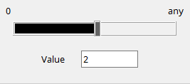
If you select “any,” you will be able to specify the value via the controller.
By specifying channels via the controller, you can reduce the number of parameters to be registered in the list. For more information, refer to the “DME7 Remote Control Protocol Specifications.” -
[Min]/[Max]
Enable you to specify the range of parameters that can be manipulated from the controller. In the case of level-type parameters for which a Min/Max value can be specified, clicking this will open a dialog box where you can specify the range. -
[Type]
Shows the type of component that has the parameter registered in the list. -
[Cmp ID]
Indicates the component ID. This ID appears at the end of the component name in the “Parameters” area.
-
 button
Enable you to navigate pages back and forth. -
Menu options that appear when you click the [
 ] menu or right-click in the dialog box
-
Find
Opens the component editor for the parameter or meter on the currently-selected row. -
Cut
Cuts the currently-selected row. -
Copy
Copies the currently-selected row. -
Paste
Pastes the copied row. -
Insert
Inserts the copied row. -
Delete
Deletes the currently-selected row. -
Swap
Swaps the position of the currently-selected row.
-
-
[Clear] button
Clears the currently-selected row. You can use < Ctrl > or < Shift > to select multiple items. -
[Clear All] button
Clears all registered parameters or meters. -
[Export] button
Exports the list in .csv format file. -
[Search] button
Opens the “Search” dialog box for searching the list in the “Remote Control Setup List” dialog box. -
[String Display]/[Numeric] button
Switch view mode in the [MIN] and [MAX] columns.
String Display: The format used in the component editor is displayed.
Numeric: The internal value is displayed. -
[OK] button
Enables the settings and closes the dialog box. -
[Cancel] button
Closes the dialog box without updating the settings. -
[Apply] button
Updates the new settings.
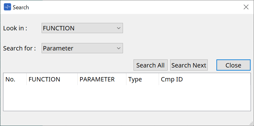
■ “Search” dialog box for searching the list
Use this when you want to search within the list of the “Remote Control Setup List” dialog box.
-
[Look In:] list box
Selects the location to search. -
[Search for:] text box / list box
A list box appears if you selected [FUNCTION] in the [Look In:] list box; otherwise, a text box appears.
Select the item to search, or enter text. -
[Search All] button
Searches the list for the specified conditions, and shows the results below.
When you click an item in the displayed search results, the focus moves to the corresponding item in the “Remote Control Setup List” dialog box. -
[Search Next] button
Searches the list for the specified conditions, and moves the focus to the item that was found in the “Remote Control Setup List” dialog box. When you click this button again, the focus moves to the next search result item. -
[Close] button
Closes the dialog box.
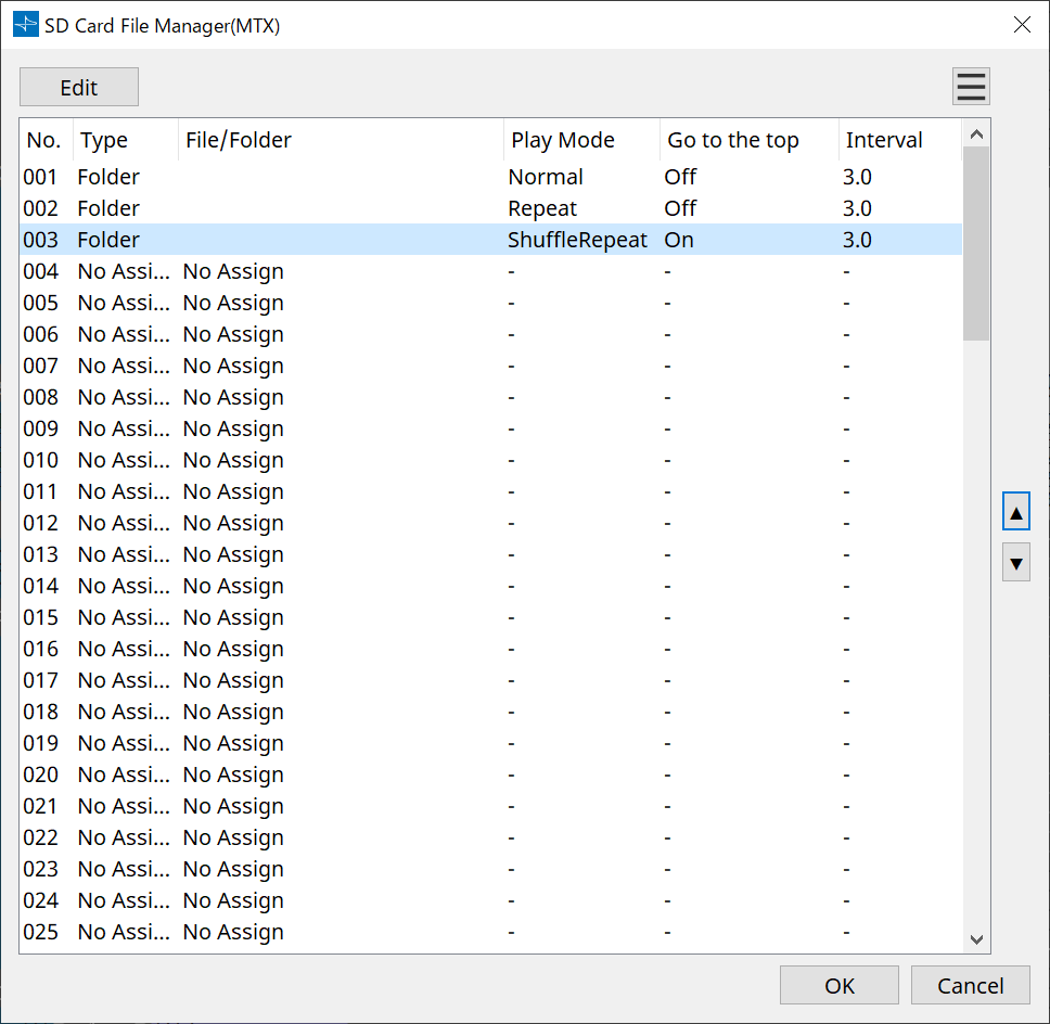
13.17.3. "SD Card File Manager" dialog box
To open this dialog box, click [SD Card File Manager] from the [Tools] button in the “Device” sheet.
This dialog box enables you to register a file you wish to play with the SD Card component.
The list in this dialog box is also used to play files via the DCP or GPI.
-
[Edit] button
Click this button to open the “SD Card File Settings” dialog box. -
Menu
 button
Click this button to open the following context menu.-
Copy
Copies the settings for the currently-selected row. -
Paste
Pastes the copied contents to the currently-selected row or to the “SD Card File Manager” dialog box for other devices. -
Clear
Deletes the settings for the currently-selected row. -
Copy All
Copies all settings. -
Clear All
Deletes all settings.
-
-
List
If no file or folder is specified, “No Assign” appears.-
No
You can set from row 001 up to row 100. -
Type
If you selected “Play 1 Song” for “File/Folder” in the “SD Card File Settings” dialog box, “1 Song” will appear in this column. If you selected “Play all songs in a folder,” “Folder” will appear in this column. -
File/Folder
Indicates the file name or folder name. -
Play Mode
Indicates the specified Play Mode. -
Go to the top
Indicates the setting that was specified in the [Go to the top when playback stops] check box. -
Interval
Indicates the interval time.
-
-
Up and down arrow
 buttons
Change the position of the currently-selected row. -
[OK] button
Saves the settings and closes the dialog box. -
[Cancel] button
Closes the dialog box without saving the changes.
"SD Card File Settings" dialog box
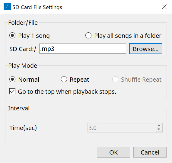
【Folder/File】
Specifies the file to play.
-
[Play 1 song] / [Play all songs in a folder] option button
If you choose [Play 1 song], only the file currently selected in [SD CARD:/] will play.
If you select [Play all songs in a folder], all files saved in the folder selected by [SD CARD:/] will play. -
[SD CARD:/]
This shows the name of the file or folder that will be played. You can change the name, or enter it directly.
If [Play 1 song] is selected
The following file and folder formats can be shown.-
(folder name)\(file name).mp3
-
(folder name)\(file name).wav
-
(file name).mp3
-
(file name).wav
-
-
If [Play all songs in a folder] is selected
The following folder formats can be shown.-
(folder name)
-
blank
-
|
- Only first-level folders are valid.
- If the folder name is blank, all the files that exist in the root level of the SD memory card will be played (folders below the root level will not be included). |
-
[Browse] button
When you click this, a screen will appear, allowing you to select the file or folder to be played.
If you choose [Play 1 song], select a file.
If you choose [Play all songs in a folder], select a folder.
【Play Mode】
-
[Normal]/[Repeat]/[Shuffle Repeat]
This specifies the play mode for the file or files.
If you choose [Normal], the specified file or files in the folder will play once.
If you choose [Repeat], the specified file or files in the folder will play repeatedly.
If you choose [Shuffle Repeat], the files in the specified folder will play repeatedly in random order. If you choose [Play 1 song] in [Folder/File], the [Shuffle Repeat] setting will be unavailable. -
[Go to the top when playback stops.] check box
When you stop file playback, this specifies whether the file will pause at the location where you stopped or will return to the beginning of the file.
If this is On, playback will begin from the beginning of the file or the first file in the folder the next time you start playback.
If this is Off, playback will begin from the location at which you stopped the next time you start playback.
【Interval】
This specifies the playback spacing when files are played consecutively.
-
Time (sec)
You can set the time in the range from 0.0 sec to 10.0 sec in 0.1 sec steps.
| If an event to play another file is executed while the current file is still playing, the current playback will stop and the other file will start to play. |
-
[OK] button
Saves the settings and closes the dialog box. -
[Cancel] button
Closes the dialog box without saving the changes.
13.17.4. "GPI" dialog box
To open this dialog box, click [GPI] from the [Tools] button in the “Device” sheet.
GPI stands for General Purpose Interface. By using the GPI input/output, you can remotely control the DME via custom-made controllers or external devices. A controller that is connected to the GPI input connector can be used to switch snapshots on the DME or to control the parameters of components.
Display devices such as LEDs and lamps or external control equipment made by other manufacturers can be connected to the GPI output connector, letting you control the external device according to the state of presets or parameters.
For hardware-related details such as how to connect the [GPI] connector, refer to the owner’s guide of each unit.
There are two methods to set up the GPI input.
・ Using the “GPI Input” dialog box, which you can access from the [Tools] button in the “Device” sheet.
Use this method to execute a single function via a single port input.
・Adding the GPI Input component to the Control layer in the “Device” sheet, and using the editor to set it up.
Use this method if you wish to control multiple parameters or functions simultaneously via a single input port, or if you wish to manipulate a complex operation by combining multiple control components.
* For GPI input, both the settings in the dialog box and the settings by the GPI Input component in the Control layer will be executed simultaneously.
There are two methods to set up the GPI output.
・Using the “GPI Output” dialog box, which you can access from the [Tools] buttons in the “Device” sheet.
Use this method to output a signal via a single output port based on a single operation as the factor.
・Adding the GPI Output component to the Control layer in the “Device” sheet, and using the editor to set it up.
Use this method if you wish to output a signal via a single output port based on multiple operations as the factor, or if you wish to execute a complex operation by combining multiple control components.
* The Output Port Type setting is linked between this dialog box and the GPI Output component in the Control layer.
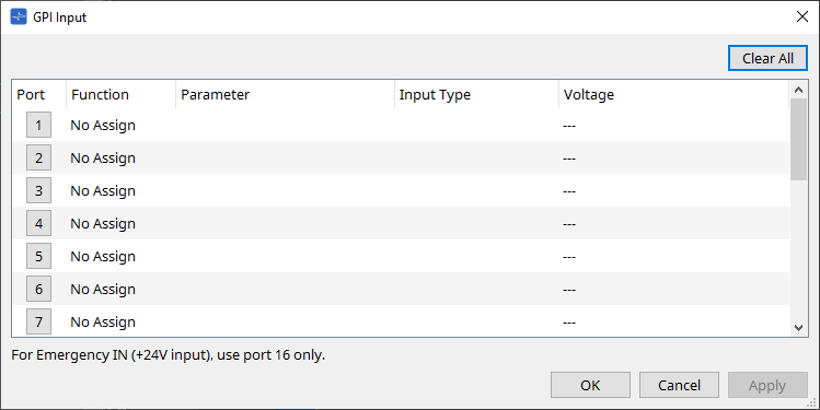
■ Operations applied to both the “GPI Input” and “GPI Output” dialog boxes
-
[Clear All] button
Initializes the settings of all ports. -
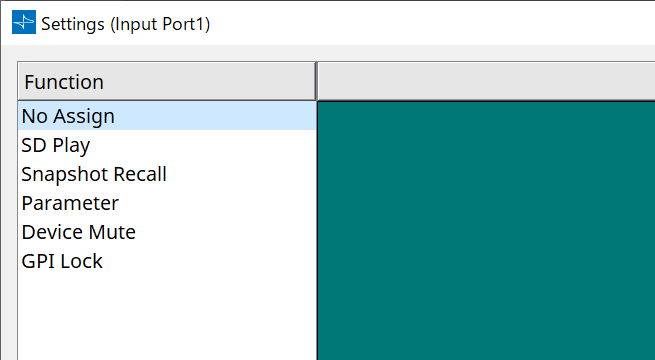
[Port] select buttons
Click this button to open the “Settings” dialog box. -
[OK] button
Applies the setting and closes the dialog box. -
[Cancel] button
Discards the setting and closes the dialog box. -
Function
Indicates the function assigned to the corresponding port. -
Parameter
Indicates the parameter assigned to the corresponding port.
■ Registering a parameter or snapshot
Drag and drop a snapshot or parameter to the green area. The Function column will automatically indicate the name of the corresponding function.
| Registration source | Registration method |
|---|---|
|
"Parameter Sets" area |
Drag and drop a snapshot to the green area. |
|
Component editor |
While pressing and holding down < Ctrl >, drag and drop a parameter to the green area. |
|
"Parameters" area |
Drag and drop a parameter in the green area. |
■ [GPI Input] dialog box
This dialog box explains how the [GPI IN] connectors on the device are configured.
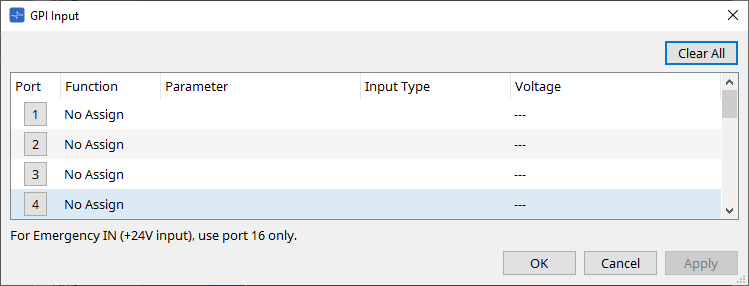
-
[Voltage]
Indicates the current input voltage value while the device is online.
Only [GPI IN] connector #16 supports Emergency In (+24V input).
Function
-
[SD Play]
-
SD Song Select & Play
Plays the file specified in the “SD Card File Manager” dialog box. -
SD Song Pause
Stops playing the file.
-
-
[Snapshot Recall]
Recalls the snapshot. -
[Parameter]
Enables you to edit the assigned parameter.When the Control Type is Parameter Value Edit
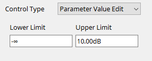
You can edit the assigned parameter within the specified range.
Click the Lower Limit or Upper Limit field to display the operator.When the Control Type is Direct Parameter Value
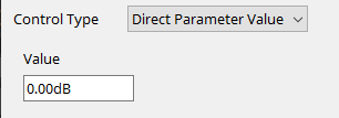
You can set the assigned parameter to a specified value.
Click the Value field to display the operator. -
[Device Mute]
Mutes the device. -
[GPI Lock]
Any inputs from the [GPI IN] ports, other than those for which GPI Lock has been set, will be disabled. -
[Emergency In]
Place the device in Emergency mode. Only port #16 supports Emergency mode.-
Emergency mode
The DME enters Emergency mode if it receives the SCP devmode emergency command, or when the input at [GPI IN] connector (IN 16) (which supports +24V) falls below 2.5V.
In this mode, the unit will operate as follows.-
The unit recalls the snapshot that was specified for [Emergency Recall] which can be accessed from [Parameter Sets]. When Emergency mode is cleared, the device returns to the status obtained prior to recall.
-
Operations from an external controller such as a DCP will no longer be received.
-
The unit will be taken offline from ProVisioniare Design.
-
-
Connection examples using the [GPI IN] connector
-
Connection example 1:
Controlling the DME with a switch
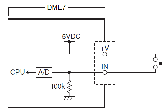
-
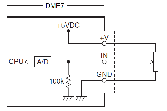
Connection example 2:
Controlling the DME with a 10kΩ B-curve variable resistor
-
[INPUT TYPE] allows the following settings.
-
 Analog
-
 Analog Inv.
-
 High Active
-
 Low Active
-
 Rising Edge
-
 Falling Edge
-
|
• The threshold value at which on/off switching will occur will be the middle value between the maximum and minimum input voltage values (the value equal to the sum of the maximum and minimum values divided by two). To prevent malfunctions, you should allow plenty of room for detection (see “GPI Calibration” dialog box).
• If the voltage has dropped because of cable length or noise, use the “GPI Calibration” dialog box to adjust the maximum and minimum input voltage values. Since voltage may become unstable, configure and set up your external circuit to ensure that there is ample distance between the maximum and minimum values. |
【
![]() Analog
】
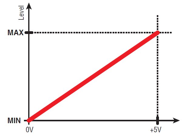
Analog
】
You can select this option if you assigned a continuously-changing parameter to the [Parameter Value Edit] category.
-
The level will be at the maximum value when the input voltage to the GPI IN is at maximum (5V), and at the minimum value when the input voltage is at minimum (0V).
【
![]() Analog Inv.
】
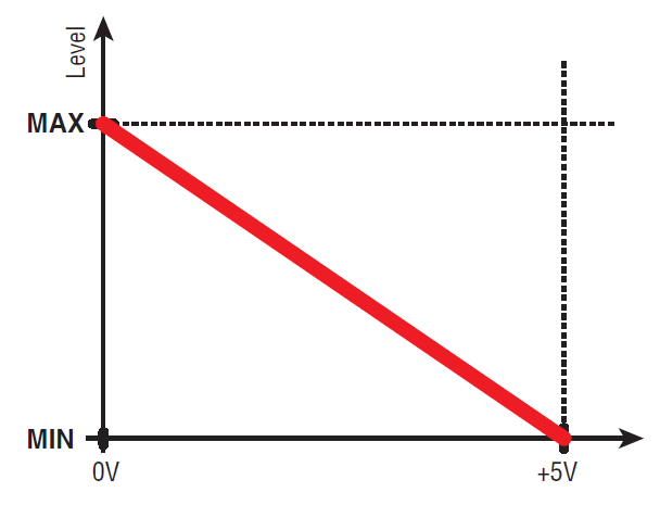
Analog Inv.
】
You can select this option if you assigned a continuously-changing parameter to the [Parameter Value Edit] category.
-
The level will be at the minimum value when the input voltage to the GPI IN is at maximum (5V), and at the maximum value when the input voltage is at minimum (0V).
【
![]() High Active
】
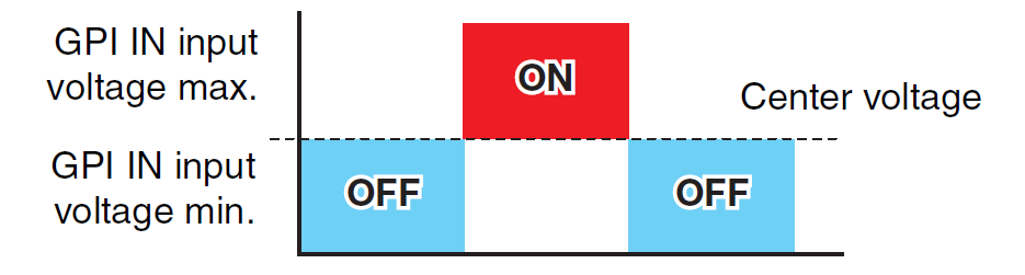
High Active
】
You can select this option if one of the following functions was assigned.
-
Device Mute
-
GPI Lock
-
The function will turn on when the input voltage to GPI IN rises above the center voltage, and will turn off when it falls below the center voltage.
【
![]() Low Active
】
Low Active
】
You can select this option if one of the following functions was assigned.
-
Device Mute
-
GPI Lock
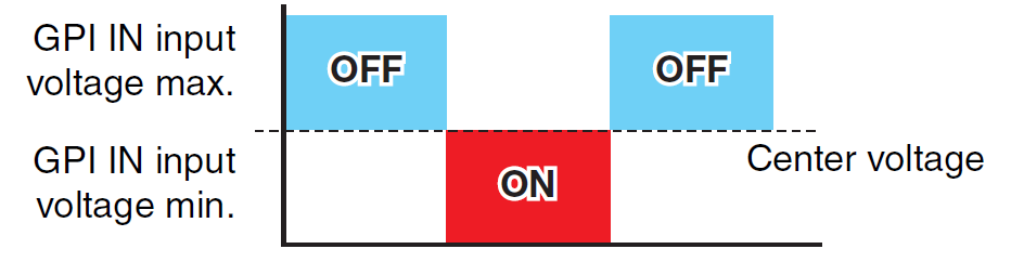
-
The function will turn off when the input voltage to GPI IN rises above the center voltage, and will turn on when it falls below the center voltage.
【
![]() Rising Edge
】
Rising Edge
】
You can select this option if one of the following functions was assigned.
-
On/Off
-
SD Song Select & Play/ SD Song Pause
-
Snapshot
-
Parameter > Direct Parameter Value
-
Device Mute
-
GPI Lock
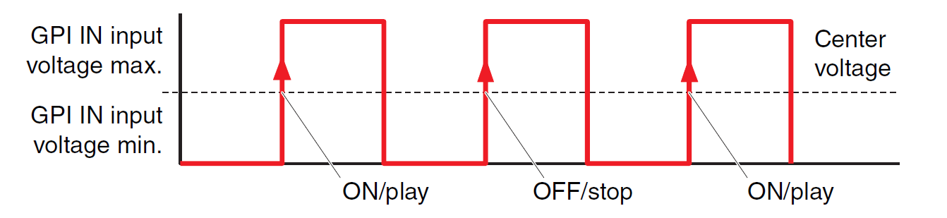
-
The assigned function will be executed if the input voltage to the [GPI IN] connector rises from below to above the middle voltage value.
【
![]() Falling Edge
】
Falling Edge
】
You can select this option if one of the following functions was assigned.
-
On/Off
-
SD Song Select & Play/ SD Song Pause
-
Snapshot
-
Parameter > Direct Parameter Value
-
Device Mute
-
GPI Lock
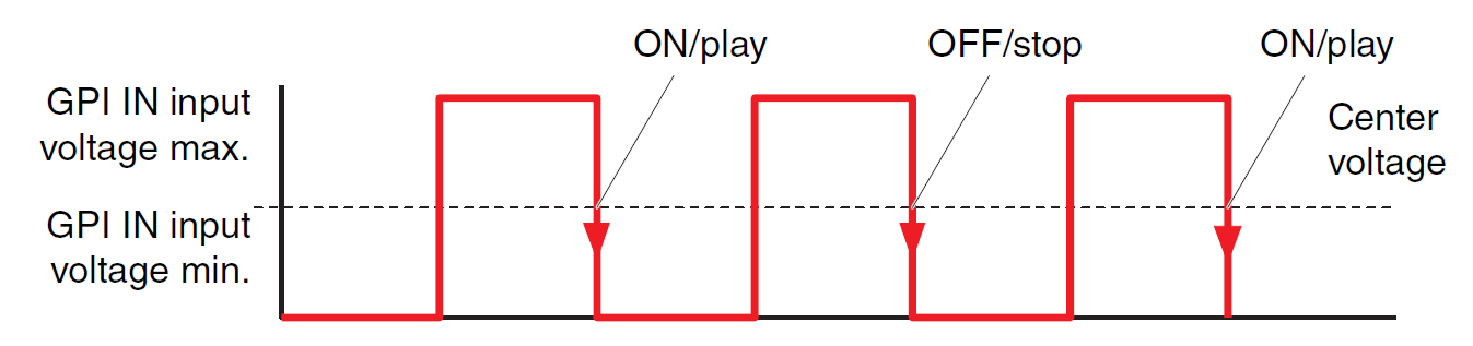
-
The assigned function will be executed if the input voltage to the [GPI IN] connector falls from above to below the middle voltage value.
■ GPI Output dialog box
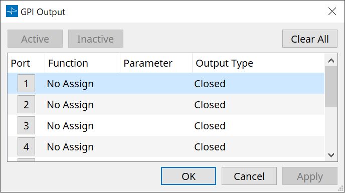
-
[Active] button, [InActive] button
Press this button while the device is online to output at the GPI output a test signal according to the Output Type setting.
For more information, refer to the explanation in the Output Type section.
Function
-
[SD Song Play]
The command will be output from the [GPI OUT] connector when an SD card file starts to play. -
[Parameter]
The command will be output at the [GPI OUT] connector when the parameter value reaches the specified status. -
[GPI Lock]
The GPI Lock status will be output at the [GPI OUT] connector. -
[Alert]
The command will be output at the [GPI OUT] connector when a specified alert occurs.
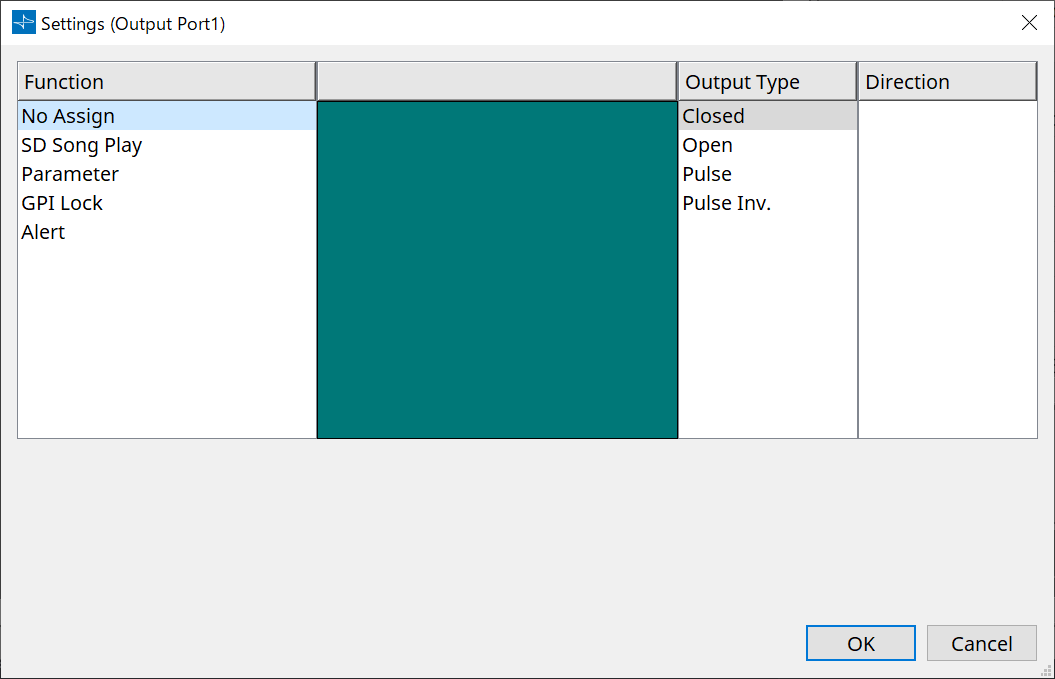
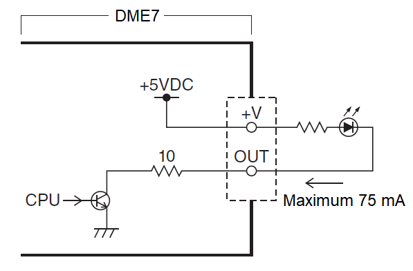
■ Output Type
Connection examples using the [GPI OUT] connector
-
[OUTPUT TYPE] allows the following settings.
-
 Closed
-
 Open
Open
-
 Pulse
Pulse
-
 Pulse Inv.
-
-
Closed
When the selected [Function] state occurs, the contact will be closed.
If [Parameter Value Edit] is selected, the contact will be closed when the specified threshold is exceeded.
If [Direct Parameter Value] is selected, the contact will be closed when the specified value is reached.-
Press the [Active] button to close the contact.
-
Press the [InActive] button to open the contact.
-
-
Open
When the selected [Function] state occurs, the contact will be opened.
If [Parameter Value Edit] is selected, the contact will open when the specified threshold is exceeded.
If [Direct Parameter Value] is selected, the contact will open when the specified value is reached.-
Press the [Active] button to open the contact.
-
Press the [InActive] button to close the contact.
-
-
Pulse
If the [Direction] is [Upward], the contact will change from closed to open for approximately 250 ms when the selected [Function] state occurs.
If [Parameter Value Edit] is selected, the contact will change from open to closed for approximately 250 ms when the value exceeds the threshold.
If the [Direction] is [Downward], the contact will change from closed to open for approximately 250 ms when the selected [Function] state is cleared.
If [Parameter Value Edit] is selected, the contact will change from open to closed for approximately 250 ms when the value falls below the threshold.-
Press the [Active] button to open the contact for 250 ms.
-
The [InActive] button is disabled.
-
-
Pulse Inv.
If the [Direction] is [Upward], the contact will change from closed to open for approximately 250 ms when the selected [Function] state occurs.
If [Parameter Value Edit] is selected, the contact will change from closed to open for approximately 250 ms when the value exceeds the threshold.
If the [Direction] is [Downward], the contact will change from closed to open for approximately 250 ms when the selected [Function] state is cleared.
If [Parameter Value Edit] is selected, the contact will change from closed to open for approximately 250 ms when the value falls below the threshold.-
Press the [Active] button to open the contact for 250 ms.
-
The [InActive] button is disabled.
-
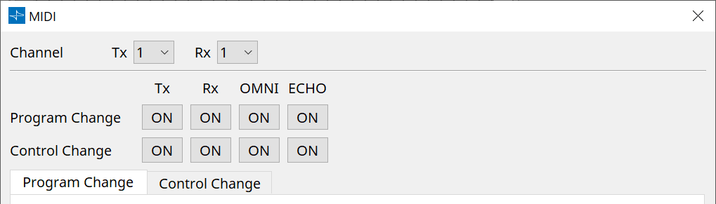
13.17.5. "MIDI" dialog box
To open this dialog box, click [MIDI] from the [Tools] button in the “Device” sheet.
You can control the DME via MIDI. You can also control the setting from the DME.
In addition, you can edit the settings while the device is online.
■ Assigning items to the list
You can assign items to the list using one of the following methods.
| Registration source | Registration method |
|---|---|
|
"Parameter Sets" area |
Drag and drop a snapshot to the green area of the "Program Change" screen. |
|
Component Editor |
While pressing and holding down < Ctrl >, drag and drop the parameter to the green area of the “Control Change” screen. |
|
"Parameter Sets" area |
Drag and drop the parameter to the green area of the "Control Change" screen. |
■ Common MIDI settings
-
Channel
-
Tx
Select from the MIDI transmit channels (1-16). -
Rx
Select from the MIDI receive channels (1-16). -
Program Change
Enables you to turn the Program Change Tx (transmit channel) and Rx (receive channel) on or off.
If OMNI is [ON], all Program Change messages will be received regardless of the receive channel setting. (This applies only to the receive channels. A single channel will be used for transmission.)
If ECHO is [ON], any Program Change messages that are received from an external device will be output unchanged. -
Control Change
Enables you to turn on or off the Control Change TX (transmit channel) and Rx (receive channel).
If OMNI is [ON], all Control Change messages will be received regardless of the receive channel setting. (This applies only to the receive channels. A single channel will be used for transmission.)
If ECHO is [ON], any Control Change messages that are received from an external device will be output unchanged.
-
-
Program Change/Control Change switching tabs
These tabs switch between the Program Change setting screen and the Control Change setting screen. -
[Clear] button
Clears the settings for the currently-selected row. -
[Clear All] button
Clears the settings for all rows.
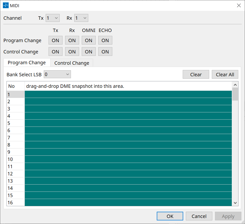
■ [Program Change] tab
Assigns shapshots to program control change numbers 1 through 128. Switches scenes when program changes are received. Up to 999 assignments can be made. Snapshots above number 128 are assigned by changing banks.
-
[Bank Select LSB] button
Banks 0-7 are available. Select from 001 to 128 for each bank. -
Program Change list
The list in the middle indicates the Program Change numbers and the current setting.-
No.
Indicates the Program Change number. -
Drag-and-drop Snapshot into this area.
Indicates the name of registered snapshots.
-
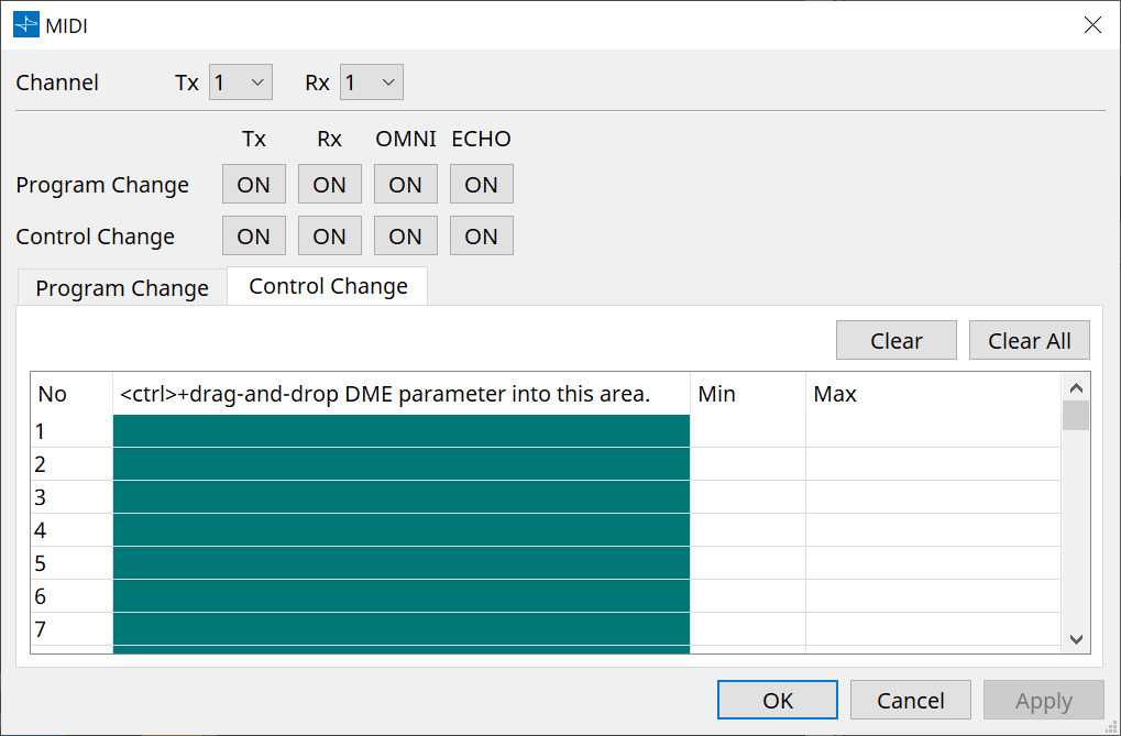
■ [Control Change] tab
Assigns components to control change for each DME. You can change DME parameters by sending control change messages from external equipment.
You can assign to control change numbers 1-31, 33-95, and 102-119.
| Because control change numbers 0 and 32 are used for bank select MSB, numbers 96-101 are RPN/NRPN related, and 120-127 are used for mode messages, they cannot be used for component assignment. |
-
Control Change List
The control change numbers and current settings are displayed in the list in the center.-
No.
Displays the control change numbers. -
< Ctrl >+drag-and-drop DME parameter into this area.
Indicates the name of registered parameters. -
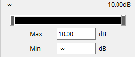
Min/Max
Enables you to specify the editable range of parameters. Click the field to display the operator.
You can change the parameter by dragging the slider.
-
13.18. Message List
Messages displayed on the DME display and countermeasures are as follows.
| Data ID | Data Name |
Message
[Normal] |
Message
[Warning] |
Message
[Error] |
Message
[Fault] |
|---|---|---|---|---|---|
|
30002 |
EXT TEMP Limit |
- |
Environmental temperature exceeded device upper limit. Please check air flow. |
- |
- |
|
30009 |
FAN
|
- |
FAN rotation speed out of control. Please check that fan rotation is not obstructed by some external impediment. |
- |
FAN stopped. Please contact Yamaha service personnel for DME7 and NEXO service personnel for DME10. |
|
30010 |
Fan
|
- |
FAN will soon reach end of expected lifespan. Please contact Yamaha service personnel for DME7 and NEXO service personnel for DME10. |
- |
- |
|
30011 |
Low Battery |
- |
Remaining battery charge is low. Please replace. |
Battery charge will soon be exhausted. Please replace. |
No battery charge remaining. Some part of data cannot be preserved correctly. |
|
30022 |
Leader W/C Unlock |
- |
- |
Wrong word clock detected on leader word clock source. |
- |
|
30024 |
Storage Lifespan Warning |
- |
Storage device will soon reach end of expected lifespan. Please contact Yamaha service personnel for DME7 and NEXO service personnel for DME10. |
- |
- |
|
30025 |
Storage
|
- |
Error occurred whilst writing data to storage. |
- |
Error occurred while writing data to storage. Please contact Yamaha service personnel for DME7 and NEXO service personnel for DME10. |
|
30026 |
IP Address Duplicate |
- |
- |
IP Address collision detected. |
- |
|
30033 |
Dante Module Error |
- |
- |
- |
Dante module is not responding. Refer to the following. |
|
Make sure that Dante Slot and the Dante module are on the same network. If they are not on the same network, communication between Dante Slot and the Dante module will not be possible. Set the IP address appropriately using the following method. If the problem persists, please contact Yamaha service personnel for DME7 and NEXO service personnel for DME10.
|
|||||
|
30034 |
No Dante Connection |
- |
No network is connected to the Dante port. Please check the Dante connection. |
- |
- |
|
30037 |
Wrong Dante Clock |
- |
Dante word clock settings are wrong. Please check the settings. |
- |
- |
|
30038 |
Muted - Dante Clock Err. |
- |
- |
Muted due to incorrect Dante word clock settings. Please check Dante word clock settings. |
- |
|
30039 |
Dante Clock Offset Err. |
- |
Dante Clock Frequency Offset is unstable. Please check network configuration including Ethernet switch settings. |
- |
- |
|
30040 |
Dante Redundancy
|
- |
Dante Audio transmission has switched to Secondary network. |
- |
- |
|
30041 |
Dante Secondary
|
- |
The Dante secondary port is not functioning. |
- |
- |
|
30047 |
Power ON |
Power ON |
- |
- |
- |
|
30049 |
Device Initialized |
Memory initialization performed. |
- |
- |
- |
|
30050 |
Time Synchronized |
Date and time is synchronized. |
- |
- |
- |
|
30051 |
Firmware Updated |
Firmware update performed. |
- |
- |
- |
|
30052 |
Scene/Snapshot Store |
Scene/Snapshot store performed. |
- |
- |
- |
|
30053 |
Scene/Snapshot Recall |
Scene/Snapshot recall performed. |
- |
- |
- |
|
30056 |
PSU Switched Over |
- |
Either Redundant Power Supply "A" or "B" failed. Please check power cables and source. |
- |
- |
|
30057 |
Dante Link 100Mbps |
- |
Dante link speed is less than Gigabit. Try plugging into a different network switch or a different port. Alternatively, try using a different network cable. |
- |
- |
|
30058 |
Sub Module Error |
- |
- |
- |
Internal sub module is not responding. Please contact Yamaha service personnel for DME7 and NEXO service personnel for DME10. |
|
30059 |
Sub Module Rebooted |
- |
- |
Internal sub module has rebooted unintentionally. |
- |
|
30060 |
Illegal MAC address |
- |
- |
- |
Illegal MAC address has been detected at control ethernet interface. Please contact Yamaha service personnel for DME7 and NEXO service personnel for DME10. |
|
30061 |
Dante MAC Address Err. |
- |
- |
- |
Illegal MAC address has been detected at Dante ethernet interface. Please contact Yamaha service personnel for DME7 and NEXO service personnel for DME10. |
|
30062 |
IP Address Assigned |
IP address is assigned to the network interface. |
- |
- |
- |
|
30063 |
IP Address Assigned (Auto IP) |
IP address is assigned (AutoIP) to the network interface. |
- |
- |
- |
|
30064 |
IP Address Released |
IP address assigned by DHCP server is released. |
- |
- |
- |
|
30065 |
Internal Network
|
- |
- |
Unable to establish connection with internal sub module due to incorrect network address. |
- |
|
30066 |
Dante (TX) Overflow |
- |
- |
Dante Audio Flow Resource (TX) exceeded. Please re-design Dante patch to match Dante Flow resources. |
- |
|
30067 |
Dante (RX) Overflow |
- |
- |
Dante Audio Flow Resource (RX) exceeded. Please re-design Dante patch to match Dante Flow resources. |
- |
|
30068 |
Dante Settings Locked |
- |
Unable to apply Dante setting changes to the Dante module due to Dante Device Lock or DDM permission settings. |
- |
- |
|
30069 |
DCP Comms Error |
- |
- |
Communication error is detected during the communication sequence between host device and DCPs. Please make sure that the following are within specification:
|
- |
|
30070 |
DCP Configuration
|
- |
- |
Unable to communicate with connected DCPs correctly. Please check if
|
- |
|
30071 |
DSP Resource Overflow |
- |
- |
The resource for audio signal processing is unexpectedly overflowed, which might cause audible noise. |
- |
|
30072 |
Incompatible Data/File |
- |
- |
Unable to Load/Import Data/File due to incompatible data format. |
- |
|
30073 |
Incompatible RC Protocol |
- |
- |
Unable to communicate/respond to external remote control device/software due to incompatible protocol version. |
- |
|
30074 |
DHCP Server No Response |
- |
- |
DHCP server is not responding to the device. |
- |
|
30075 |
NTP Server No Response |
- |
- |
NTP server is not responding to the device. |
- |
|
30076 |
Missing License |
- |
- |
Some or entire functions of this device stop working due to missing or insufficient licenses. Please activate additional licenses or remove corresponding functions. |
- |
|
30077 |
Setting Data
|
- |
- |
Corrupted data/file is detected. |
- |
|
30078 |
Storage Full |
- |
- |
Storage Full. |
- |
|
30079 |
Unsupported
|
- |
- |
The storage drive is formatted with unsupported file system type. Please re-format the storage to a supported format. |
- |
|
30080 |
Removable Drive Mounted |
Removal drive has been mounted to device. |
- |
- |
- |
|
30081 |
Removable Drive Unmounted |
Removal drive has been unmounted from device. |
- |
- |
- |
|
30082 |
File Not Found |
The file cannot be found. |
- |
- |
- |
|
30083 |
Authentication Failed |
- |
Wrong PIN code/Password was entered. |
- |
- |
|
30084 |
Panel Locked |
The operation panel is locked. |
- |
- |
- |
|
30085 |
Panel Unlocked |
The operation panel is unlocked. |
- |
- |
- |
|
30086 |
Scene/Snapshot
|
- |
- |
Failed to recall the Scene/Snapshot data. |
- |
|
30087 |
Data Sync Failed |
- |
- |
Synchronization sequence has been stopped unexpectedly. |
- |