Powered Speakers DZR/DXS-XLF Series
23. Powered Speakers DZR/DXS-XLF Series
23.1
Overview
23.2
"Project" Sheet
23.3
Tuning Sheet
23.4
Device Sheet Screen Configuration
23.5
Presets Area
23.6
Context Menu
23.7
Alert List
23.8
Component Editor
23.1. Overview
The DZR/DXS-XLF series is Yamaha’s flagship powered speaker, which delivers best-in-class sound pressure levels and sound quality through high-power amplifiers and 96 kHz signal processing. Only Dante models are supported.
23.2. "Project" Sheet
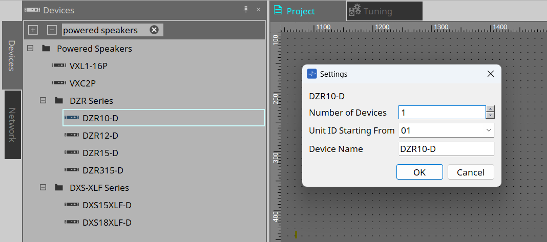
This is the sheet on which devices are placed. When placing devices, the Settings screen shown below is displayed.
-
Number of Devices
Select the number of devices to be placed on the sheet. -
Unit ID Starting From
The starting number for the device Unit IDs can be selected. -
Device Name
The device name can be displayed and edited.
23.2.1. Properties Area
This area allows you to display and edit device information. The following section explains "Input Source Redundancy". For other settings, refer to the DZR/DXS-XLF Series reference manual.
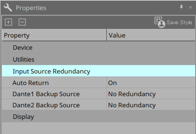
Input Source Redundancy
If the audio on the primary line (Dante) is cut off due to a problem such as an input device failure, the line will automatically switch to the backup line (Analog). When the input audio returns, the original line is automatically restored.
| Input Source Redundancy is a function that is independent from the Dante network redundancy function. |
Dante INs (1 to 2) are used as the primary lines, and Analog Ins (1 to 2) are used as the backup lines.
The channel combinations are fixed.
| PRIMARY SOURCE | BACKUP SOURCE |
|---|---|
|
Dante IN 1 |
Analog In 1 |
|
Dante IN 2 |
Analog In 2 |
-
Auto Return
When this option is turned on, the input line will automatically switch back to the primary line when the primary line is restored.
When this option is off, you can manually switch back the line by executing MANUAL RETURN on the main unit or by pressing the [Return] button in ProVisionaire Design. -
Dante Backup Source
Select a Backup Source (Analog 1, 2) to enable the Input Source Redundancy function. The channel combinations are fixed.
23.3. Tuning Sheet
The Tuning sheet allows you to set parameters (such as EQ and Delay) for grouped channels collectively. For details about the sheet, refer to Tuning Sheet .
| The maximum number of units that can be registered per group is 32 for the DZR series and 16 for the DXS-XLF series. |
23.3.1. Link Group Editor
This is the parameter setting screen for link groups. To display the editor, display the Tuning sheet and double-click the link group to which the DZR series channels are registered, or right-click the group and select [Open Link Group Editor].
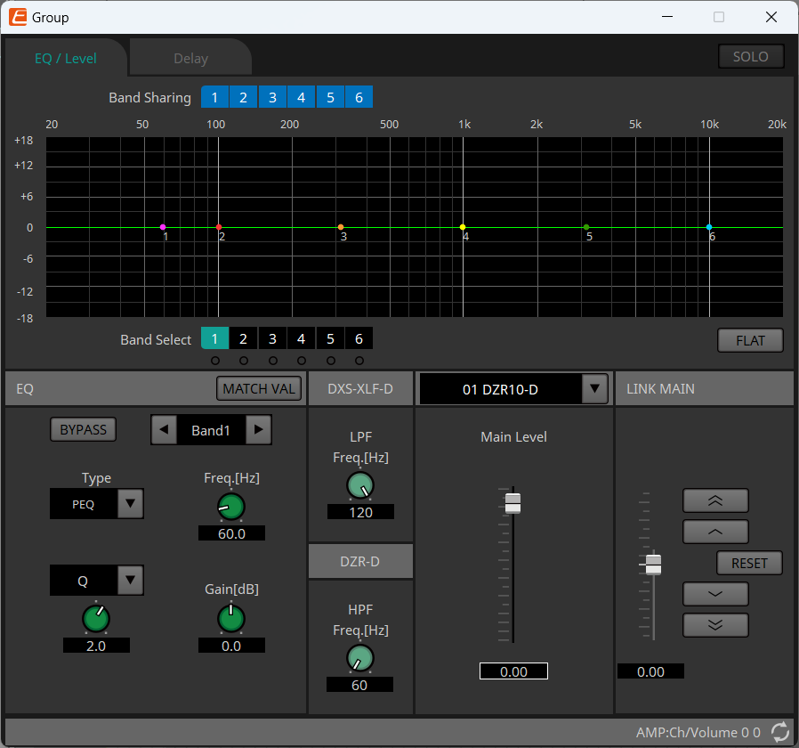
-
[SOLO] button
This button is enabled by turning on the [Solo Mode] button on the toolbar when in the online state.
When this button is turned on, audio will be output only from the channels registered in this link group, which is useful for final adjustments to EQ, volume, and Delay.
When audio is muted by using the SOLO function, [MUTE] of the Speaker Out component is turned on.
23.3.2. [EQ/Level] Tab
This tab allows you to change the EQ, HPF, and LPF of the devices registered in a group at once to the same values.
It also allows you to change the Main Level of the devices registered in the group at once by a relative value.

-
[Band Sharing] button
If a certain device is registered in multiple groups, click these buttons to select the band occupied by each group. Occupied bands are shown in blue. Bands whose numbers are not white are occupied by other groups and cannot be selected or operated. Releasing an occupation is possible only in the link group editor that occupies the band. -
[MATCH VAL] button
This button copies the EQ settings of the occupied bands in the link group editor to the registered devices. -
Main Level
This is the actual Main Level value of the selected device. -
LINK MAIN
Adjust the Level of the devices in a link group by a relative value. The movable range is displayed as a vertical gray line. Right-click a fader and select [Match Values] to set the Level of the members of a link group to the same value.
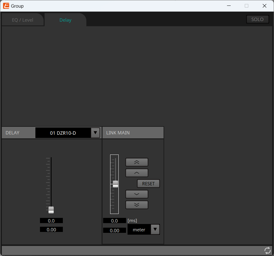
23.3.3. [Delay] Tab
This tab allows you to change the Delay of the devices registered in a group at once by a relative value.
-
DELAY
This is the actual Delay value of the selected device. -
LINK MAIN
Adjust the Delay of the devices in a link group by a relative value. The movable range is displayed as a vertical gray line. Right-click a fader and select [Match Values] to set the Delay of the members of a link group to the same value.
For an explanation of the other buttons, refer to Tuning Sheet of the PC series.
23.4. Device Sheet Screen Configuration
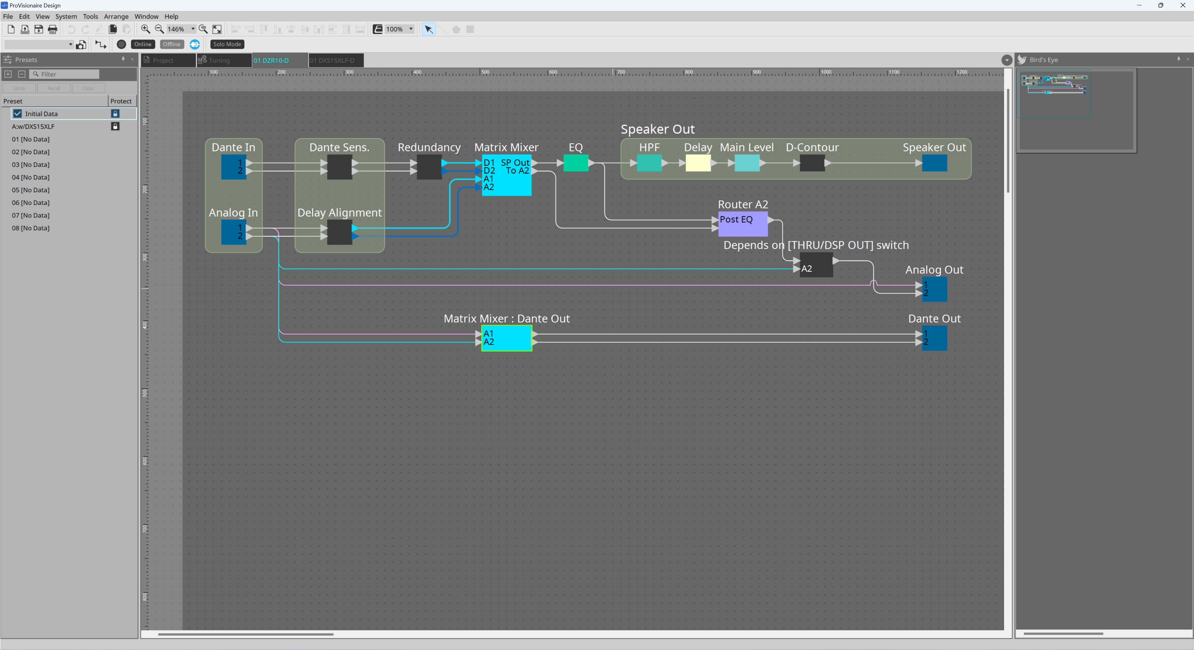
When you open the device sheet for the DZR/DXS-XLF series, the Presets area and the Bird’s Eye view area are displayed.
Double-click a component on the device sheet to open the component editor.
-
Presets Area
Multiple parameter settings can be stored as a preset. -
Bird’s Eye view
Displays a full view of the sheet.
23.5. Presets Area
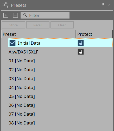
In this area, you can store multiple parameter settings as a preset. By recalling the preset, the parameters stored in the preset can be deployed. The parameters of the currently deployed preset are called the current parameters.
To simultaneously recall a preset on multiple devices, click the
 button and configure the settings in the
Linked Presets Manager dialog box
.
| Editing operations, such as storing, recalling, and clearing presets, are only possible when ProVisionaire Design is connected to the device. |
-
[Store] button
This button is for storing presets. -
[Recall] button
This button is for recalling presets. -
[Clear] button
This button is for clearing presets. -
Preset list
Displays the list of presets.-
Initial Data
Restores the initial settings. This is a call-only preset. -
Factory preset
When using the DZR series and DXS-XLF series in combination, you can optimize the crossover frequencies, levels, and delay values by calling the presets named after each model. This is a call-only preset. -
User preset list
Up to eight presets can be saved. You can call, save, erase, edit titles, and set protection.
-
-
Protect
When you click the lock icon , the image changes to
 , and the preset becomes protected from being edited or cleared.
If you click the icon while the preset is protected, the preset becomes unprotected.
Call-only presets are always protected.
23.6. Context Menu
The following describes the contents of the context menus that are displayed when you right-click each area.
23.6.1. Tuning Sheet
When you right-click on the Tuning sheet, the following context menu appears.
| Menu item | Details |
|---|---|
|
[Select All] |
[All Link Groups]
|
|
[Close All Editor Windows] |
Closes all editors. |
|
[Snap to Grid] |
Put a check by this item to place objects in alignment with the sheet grid. |
23.6.2. Link Group on Tuning Sheet
When you right-click on a link group, the following context menu appears. Some menu items may not be available depending on the connected device.
| Menu item | Details |
|---|---|
|
[Open Link Group Editor] |
Opens the link group editor. For details about the link group editor, refer to each device. |
|
[Open Device Sheet] |
Opens the device sheet for the selected device. |
|
[Identify] |
Makes the device display flash for a few seconds. |
|
[Delete] |
If a channel is selected, the channel is deleted from the link group.
|
|
[Bring to Front] |
Moves the link group to the frontmost position. |
|
[Send to Back] |
Moves the link group to the backmost position. |
23.6.3. Project Devices Area
When you right-click a device or channel in the Project Devices area, the following context menu appears.
| Menu item | Details |
|---|---|
|
[Find] |
Shifts the focus to the link group where the device or channel is registered. |
|
[Add to Link Group] |
Registers the device channel to the link group. If a speaker is connected to the device, the channel of the connected device will be registered. |
23.6.4. Link Groups Area
When you right-click an object in the Link Groups area, the following context menu appears.
| Menu item | Details |
|---|---|
|
[Find] |
When you have right-clicked on a device, the device in the link group becomes the focus, and the link group component editor opens.
|
|
[Delete] |
When you have right-clicked on a channel, the channel is deleted from the link group.
|
23.6.5. Device Sheet
When you right-click on the device sheet in a place without an object, the following context menu appears.
| Menu item | Details |
|---|---|
|
[Close All Editor Windows] |
Closes all editors. |
23.6.6. Components/Component Editor in the Device Sheet
When you right-click on a component or a place other than the controls of a component, the following context menu appears (with some exceptions).
| Menu item | Details |
|---|---|
|
[Open Component Editor] |
Opens the component editor. |
|
[Copy] |
Copies the parameter settings of the component editor. |
|
[Paste Parameters] |
Applies the parameter settings of the component editor that was copied. |
23.7. Alert List
The alerts that may occur on the DZR/DXS-XLF series, their details, and countermeasures are listed below.
A one-time alert is displayed when the event occurs. A continuous alert is displayed when the event begins and when it ends.
If a problem persists, contact the Yamaha repair service center listed at the end of the instruction manual for your device.
| No. | Severity |
One-time
/Continuous |
Message | Details | Countermeasures |
|---|---|---|---|---|---|
|
01 |
Fault |
Continuous |
SYSTEM ERROR |
The product is not starting properly. |
Turn off the power, wait at least 6 seconds, and turn on the power again. If the problem persists, a factory reset may resolve it. If the problem still persists, contact the Yamaha repair service center. |
|
03 |
Fault |
Continuous |
|||
|
04 |
Fault |
Continuous |
|||
|
05 |
Fault |
Continuous |
|||
|
10 |
Fault |
One-time |
|||
|
11 |
Fault |
One-time |
|||
|
12 |
Error |
One-time |
CURRENT MEMORY ERROR |
||
|
13 |
Error |
One-time |
PRESET MEMORY ERROR |
||
|
14 |
Fault |
One-time |
SYSTEM ERROR |
||
|
15 |
Error |
One-time |
|||
|
16 |
Error |
One-time |
SYSTEM ERROR (DANTE) |
This error may occur when the device firmware version and the Dante firmware version are not compatible.
|
|
|
17 |
Error |
One-time |
DUPLICATE IP ADDRESS |
The IP address is duplicated. |
Set the IP addresses so that there are no duplicates. |
|
20 |
Error |
Continuous |
OUTPUT CURRENT OVER |
The circuit is being protected from excessive amplifier output current. |
The product may be faulty.
|
|
23 |
Warning |
Continuous |
AMP TEMP TOO HIGH step2[*] |
The amplifier became too hot, so the output limiter was applied. (*: HF or LF) |
Use the device with a lower output level or wait a while until the heat subsides. Also, avoid direct sunlight to the rear panel, and ensure good ventilation around the rear panel. |
|
25 |
Error |
Continuous |
AMP TEMP TOO HIGH step3[*] |
The amplifier became too hot, so the output was muted. (*: HF or LF) |
Wait a while until the heat subsides. Also, avoid direct sunlight to the rear panel, and ensure good ventilation around the rear panel. |
|
27 |
Warning |
Continuous |
POWER SUPPLY TEMP TOO HIGH[*] |
The power supply section became abnormally hot, so the limiter was applied. (*: HF or LF) |
Continued use may damage to the power supply section. Use the device with a lower output level. |
|
34 |
Warning |
Continuous |
AMP PROTECT (LIMIT)[*] |
An abnormality occurred in the amplifier, so the output limiter was applied. (*: HF or LF) |
Wait a while until the heat subsides. If the issue does not improve even after the heat has subsided, the product may be broken. Contact the Yamaha repair service center. |
|
35 |
Error |
Continuous |
HF/OVER TEMP PROTECT (DOWN) |
An abnormality occurred in the amplifier, so the output was muted. |
|
|
42 |
Warning |
Continuous |
INPUT D[*]
|
The Input Source Redundancy function switched the audio from Dante to Analog. (*: CH number) |
Check whether the main audio line (Dante) is working properly.
|
|
43 |
Error |
Continuous |
INPUT D[*] NOT CONNECTED |
A Dante input disconnection was detected. (*: CH number) |
Check whether the Dante line is working properly. |
23.8. Component Editor
Double-click a component on the device sheet to open the component editor.
This section describes the DZR series/DXS-XLF series component editors and the dialog boxes and windows related to components. For details about other components, refer to
"ProVisionaire Design Component Guide"
.
■ DZR series
■ DXS-XLF series
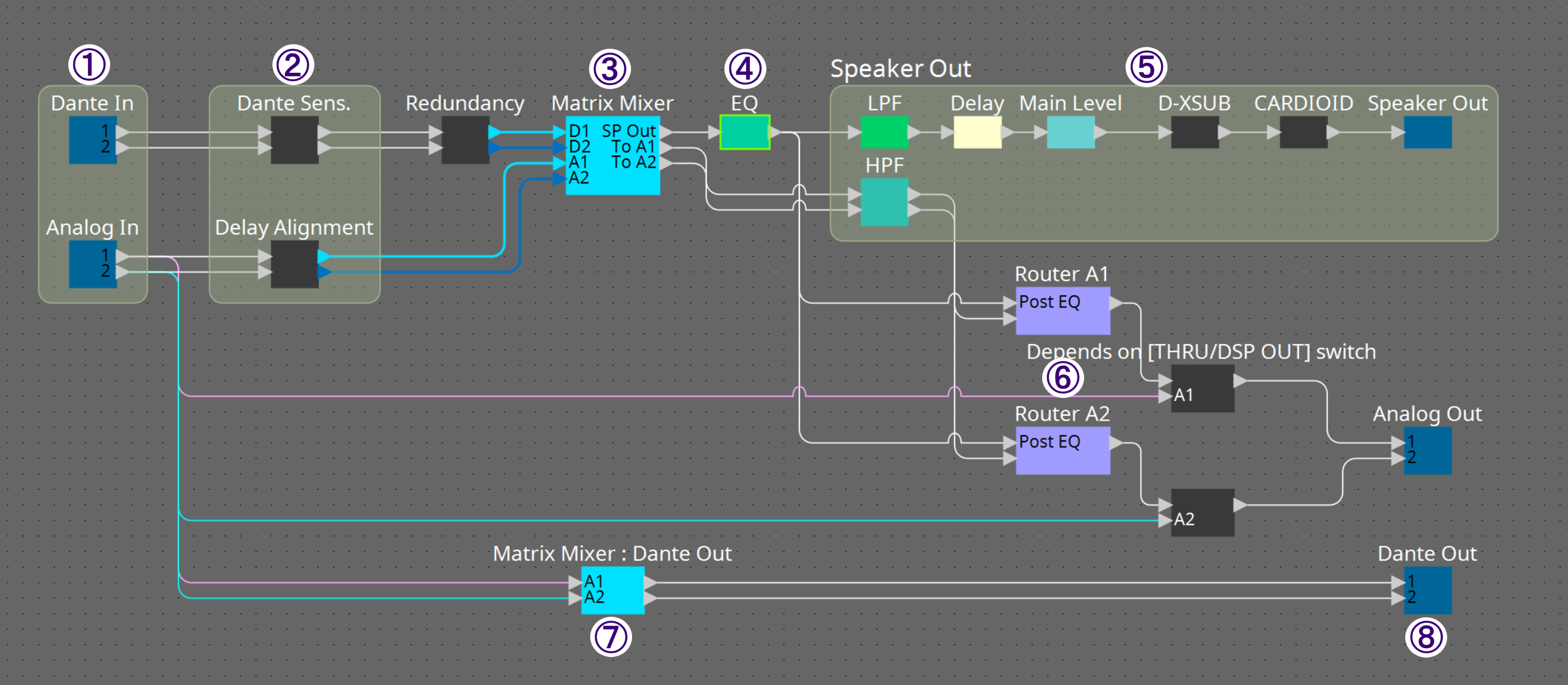
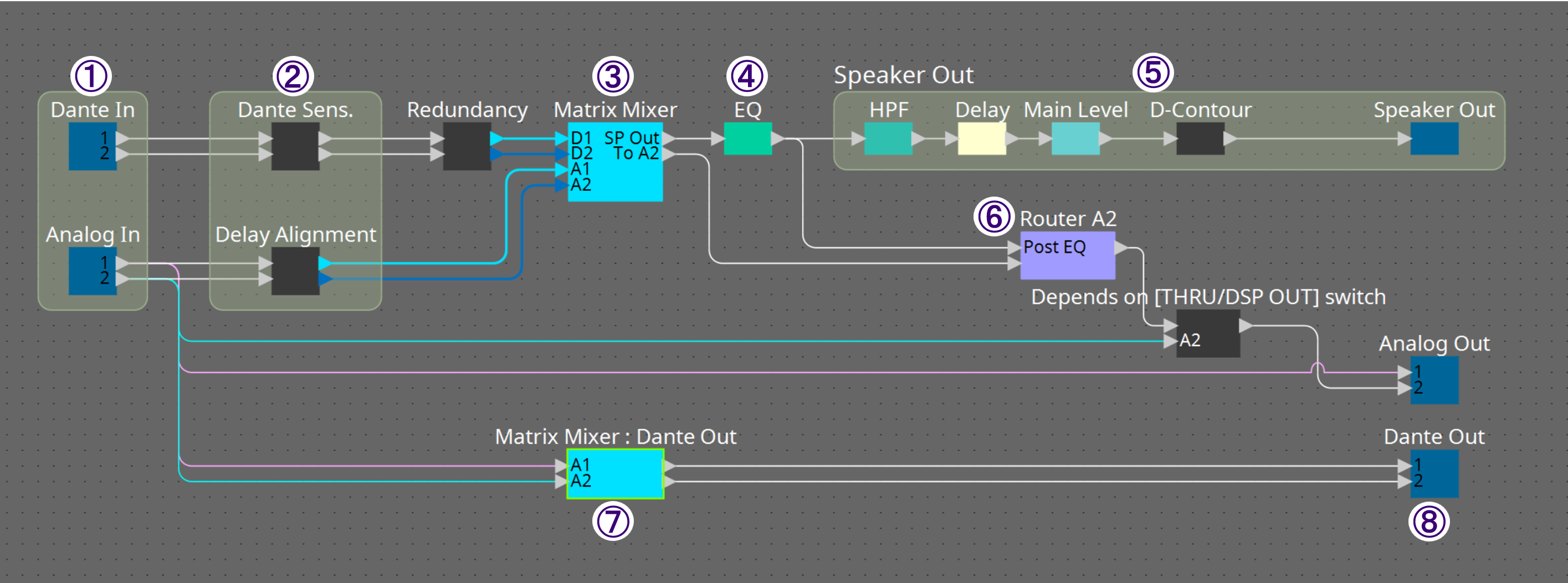
| No. | Component name | Details | Link |
|---|---|---|---|
|
① |
Input |
Adjusts the input level and displays/cancels the redundancy status. |
|
|
② |
Dante Sens./
|
Sets Dante Sensitivity and Delay Alignment. |
|
|
③ |
Matrix Mixer |
Sets the matrix. |
----- |
|
④ |
EQ |
Sets the 6-band EQ. |
|
|
⑤ |
Speaker Out
|
Sets items from HPF to D-Contour. |
|
|
⑤ |
Speaker Out
|
Sets items from LPF to D-XSUB and CARDIOID. |
|
|
⑥ |
Router |
Turns EQ on or off and adjusts the level for Analog Out. |
----- |
|
⑦ |
Matrix Mixer : Dante Out |
Sets the Dante Out matrix. |
----- |
|
⑧ |
Dante Out |
Adjusts the Dante output level. |
----- |
23.8.1. Input Component Editor
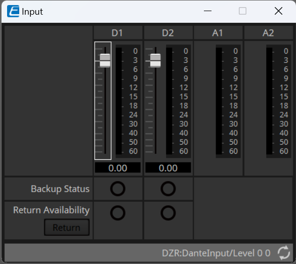
You can use the faders to adjust the Dante input levels.
-
Backup Status
Lights up when the line has switched from the primary line (Dante) to the backup line (Analog). -
Return Availability
Lights up when the primary line has been restored and the input line can be switched back to the primary line.
(Only when Auto Return = Off) -
[Return] button
When the primary line is restored, press this button to manually switch the input line back to the primary line.
(Only when Auto Return = Off)
|
When Auto Return is turned on, the line will be automatically restored.
The Auto Return setting can be changed in the Properties area of the Project sheet. |
23.8.2. Dante Sens./Delay Alignment Component Editor
-
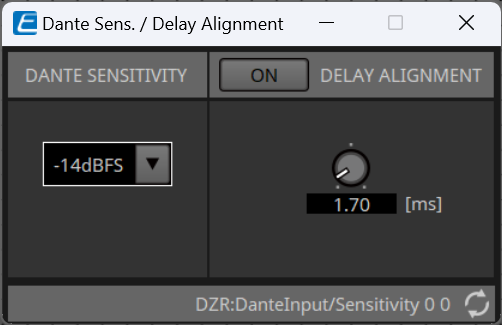
Dante Sensitivity
This component sets the input sensitivity of the digital signal from Dante when the signal is input to the amplifier section.
The input sensitivity value that you set becomes the clipping level of the speaker.
Select from -14dBFS (default) or -6dBFS. For fine adjustments, use the Input component D1 or D2.
|
If you are using an analog line as a backup for the Dante line, set the sensitivity to "-14dBFS". The volume will match when the line is switched.
Setting the sensitivity to "-14dBFS" will increase the input from Dante by 8dB, so if you are only using a Dante line, set it to "-6dBFS". Setting the sensitivity to "-6dBFS" will match the output level of the digital mixer with the input level of the DZR. |
-
Delay Alignment
Corrects the time difference between analog input and Dante input.
If you are using an analog line as a backup for the Dante line, set this option to "ON". When you set this option to "ON", the timing of the analog input will match the Dante input audio when the line is switched.
|
The appropriate delay value will vary depending on the Dante settings and the combination of connected devices.
For more information, refer to the DZR/DXS XLF Series reference manual. |
| The delay set here is applied to the analog input. Therefore, if you use a device with only an analog line, set this option to "OFF". |
23.8.3. Speaker Out Component Editor
■ DZR series
-
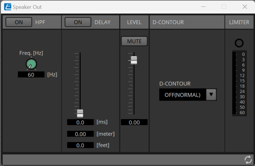
D-CONTOUR
Set the frequency characteristic best suited for the purpose of use.-
OFF (NORMAL)
Turns off D-CONTOUR. This is a general-purpose frequency characteristic setting. -
FOH/MAIN
This setting boosts the treble and bass ranges to create frequency characteristics suitable for the main speakers. The amount of boost is automatically adjusted according to the volume to achieve a well-balanced sound. -
MONITOR
This setting ensures clarity, which is important for floor monitors, and suppresses the bass range that tends to become boomy when a speaker is placed on the floor. The latency is reduced and the phase characteristics change.
-
■ DXS-XLF series
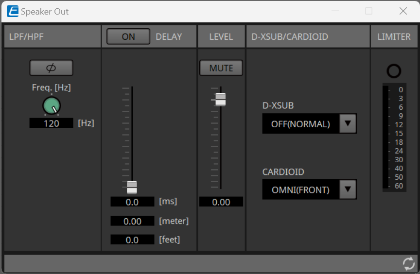
-
D-XSUB
Set the frequency characteristic best suited for the purpose of use and music genre.-
OFF (NORMAL)
Turns off D-XSUB. This is a general-purpose frequency characteristic setting. -
BOOST
This setting boosts the frequency range to emphasize a punchy feel. -
EXTenDed LF (extended LF)
This setting extends the playback frequency to lower bass ranges.
-
-
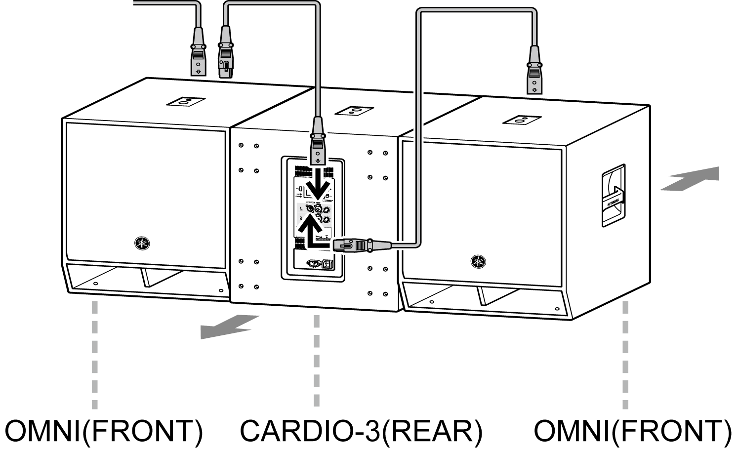
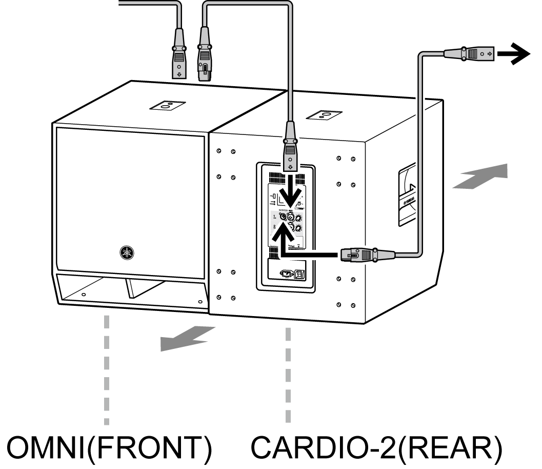
CARDIOID
This component sets the cardioid mode. Change the setting according to the orientation and number of speakers.-
OMNI(FRONT)
When cardioid mode is not used -
CARDIO-2(REAR)
Rear-facing speaker, when two speakers are used side by side
-
-
CARDIO-3(REAR)
Center, rear-facing speaker, when three speakers are used side by side
