I/O Interface RSio64-D
22. I/O Interface RSio64-D
22.1
Overview
22.2
"Project" sheet
22.3
Editor
22.1. Overview
This I/O rack can be utilized in a wide range of applications, including live sound, broadcasting, and recording, and features maximum 64 in/64 out Dante/Mini-YGDAI card conversion compatibility.
The RSio64-D is an audio interface that can convert between Dante and Mini-YGDAI formats for up to 64 inputs and 64 outputs.
22.2. "Project" sheet
This is the sheet on which devices are placed.
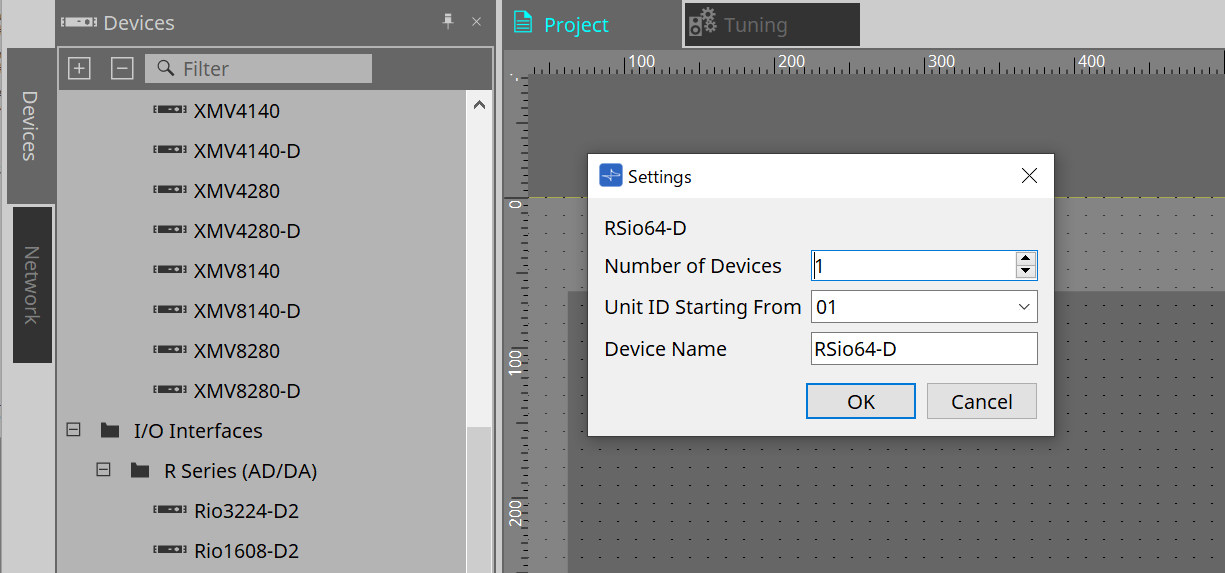
When placing devices, the Settings screen shown below will be displayed.
-
Number of Devices
Selects the number of RSio units placed on the sheet. -
Unit ID Starting From
You can select the starting number for the device Unit IDs. -
Device Name
The device name can be displayed and edited.
22.3. Editor
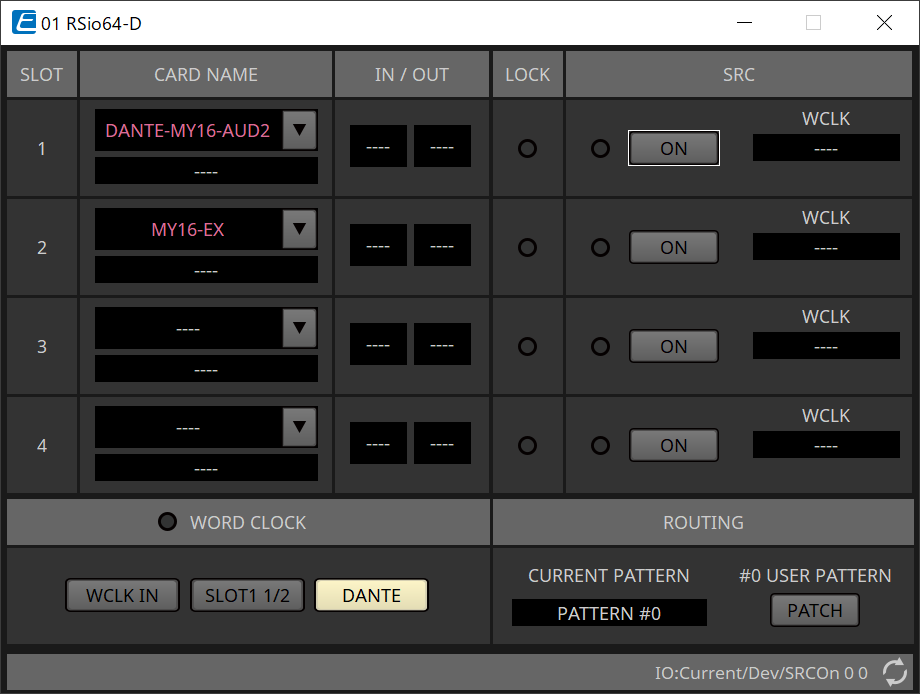
Double clicking a device on the Project sheet will directly open the editor.
-
[CARD NAME]
Upper level
Select the card you plan to install in the device.
The "Select Card" dialog opens when you click it.
Lower level
Displays the card that is actually installed in the device. -
IN/OUT PORT
This indicates the number of input and output ports for the cards installed in slots 1 to 4. If no card is installed, “--” will appear. -
[LOCK] indicators
This indicates the word clock status for slots 1 to 4. If the word clock is operating normally, this indicator will be green.
|
Unlit |
No card is installed in the slot, or an unsupported card is installed. |
|
Green
|
This indicates that a clock synchronized with the clock source selected by the WORD CLOCK select key is being input from the card.
|
|
Green
|
A valid clock is being input from the card, but is not synchronized with the clock source selected by the WORD CLOCK select key. If an external device is connected to the corresponding slot, input/output is not occurring correctly between that device and the RSio64-D. Input/output will occur correctly if SRC is turned ON. |
|
Red (lit)
|
A valid clock is not being input from the card. If an external device is connected to the corresponding slot, input/output cannot occur correctly between that device and the RSio64-D. |
|
Red
|
The frequency of the clock source selected by the WORD CLOCK select key is outside the range of operating frequencies of the card installed in the slot. Either set the frequency of the clock source to be within the operating range of the card, or turn SRC on. In the case of an analog card, turning SRC on makes the card operate at the RSio64-D’s internal frequency of 48 kHz. |
-
[SRC] indicators
These indicate the SRC (Sampling Rate Converter) status of slots 1 to 4.
|
Unlit |
SRC is off. |
|
Green (lit) |
SRC is on, and the clock selected by the SRC WCLK DIP switch is being input correctly. |
|
Red (lit) |
SRC is on, but an appropriate clock is not being input. It may be that the clock selected by the SRC WCLK DIP switch is not being input, or is outside the operating range. Either turn SRC off, or change the setting of the DIP switch. |
-
[SRC] button
For each slot, these turn SRC on/off for the slot’s input as well as output. -
WORD CLOCK source
Indicates the SRC word clock source status for slots 1 to 4 the RSio64-D.
|
[SLOT] |
When using the word clock signal being input from the card in the slot. |
|
[WCLK IN] |
When using the word clock signal being input from the WORD CLOCK IN connector on the rear panel. |
|
[CARD] |
When the SRC function in the card is on. |
|
[---] |
If there is no card in the slot. |
-
[WORD CLOCK] select button
Selects the word clock source of the RSio64-D.
|
WCLK IN |
This is lit if the RSio64-D is using the word clock that is being input from the rear panel [WORD CLOCK IN] connector. This flashes if there is no valid word clock input*1. |
|
SLOT1 1/2 |
This is lit if the channel 1/2 word clock of slot 1 is being used. This flashes if there is no valid word clock input*1. The channel 7/8 word clock is used when using the MY8-AEB*2. If the SRC on the MY8-AE96S is in use, you will be unable to use the input signal as word clock. |
|
DANTE |
This is lit if the Dante network’s word clock*3 is being used. (If no valid Dante signal is being input, the clock generated by the internal Dante module is used.) |
*1 When this is flashing, the unit uses the Dante word clock to operate and perform input/output.
*2 In order to use MY8-AEB, set AE ⇔ RSVD switch to the RSVD position.
*3 If you want to change the frequency of the Dante word clock, use Dante Controller.
-
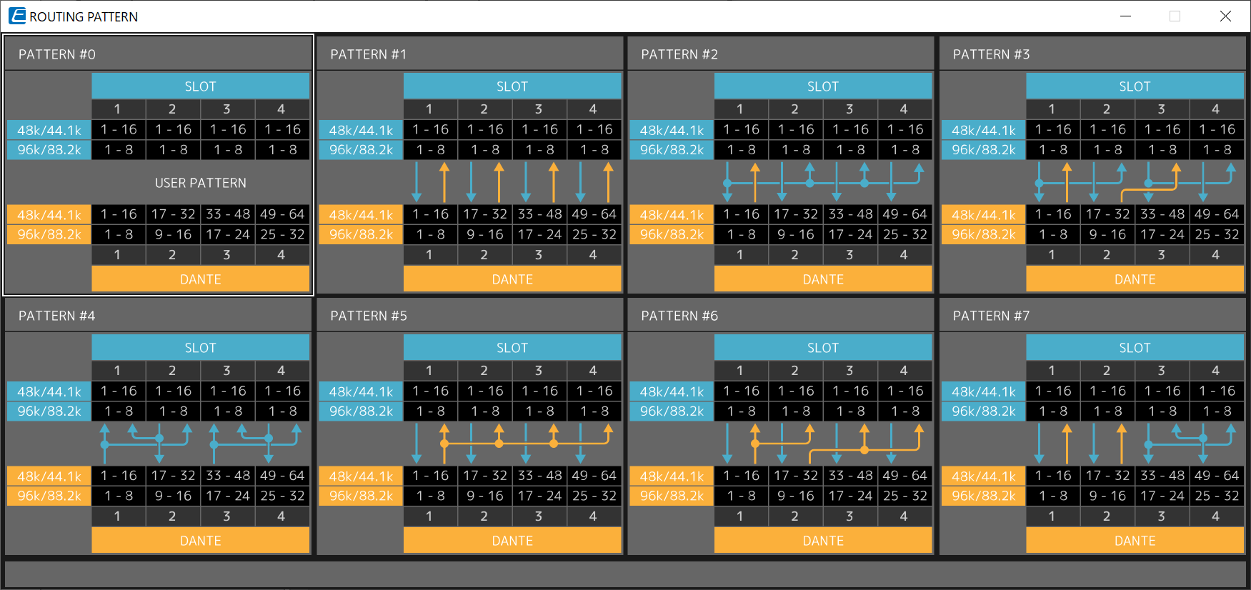
[CURRENT PATTERN] button
Displays the currently selected routing pattern on the RSio64-D. When you click on the button, the routing pattern details are displayed.
-
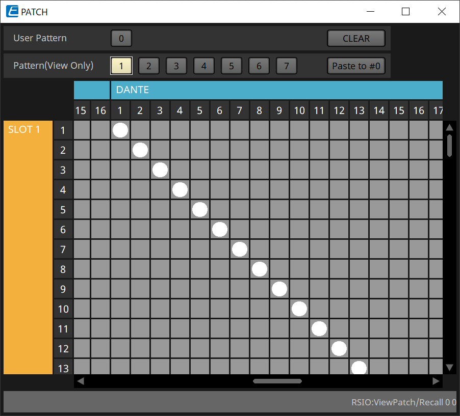
[Patch] button
When you click the button, the edit window opens.
Edits the Patch to be applied when 0 (User Pattern) is selected on the rotary switch used to select the Routing Pattern on the main unit.
-
[User PATTERN] / [Pattern(View Only)] button
When User Pattern is selected, the patch can be edited.
When Pattern (View Only) is selected, seven types of templates are called. They cannot be edited.
When you click the [Paste to #0] button while Pattern (View Only) is selected, the template is copied to User Pattern.
When editing, please use the template as a basis.-
[CLEAR] button
When you click this while User Pattern is selected, all of the patches will be cleared.
-