Power Amplifiers PC-series
18. Power Amplifiers PC-series
18.1
Overview
18.2
"Project" sheet
18.3
"Tuning" sheet
18.4
Device sheet screen configuration
18.5
"Presets" area
18.6
Context Menu
18.7
Alert list
18.8
Component editors
18.1. Overview
By combining the powerful 20×8 input matrix functions of the PC-D/DI series amplifiers with Dante I/O, the versatility of any system can be dramatically increased.
Not only can the PC-D/DI’s input matrix function be an auxiliary matrix that expands the entire system, but by allowing direct audio signal input from other analog devices or Dante-equipped devices even in systems without additional mixers or DSPs, even more flexible routing becomes possible.
18.2. "Project" sheet
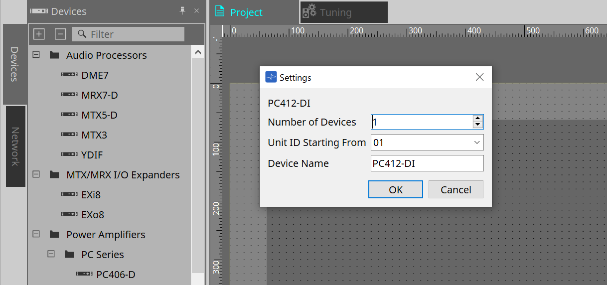
This is the sheet on which devices are placed. When placing devices, the Settings screen shown below is displayed.
-
Number of Devices
Selects the number of PC series units placed on the sheet. -
Unit ID Starting From
You can select the starting number for the device Unit IDs. -
Device Name
The device name can be displayed and edited.
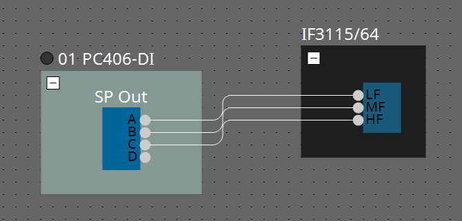
18.2.1. PC-D and speaker connections
If you drag and drop speakers from the Devices area, any speaker can be added to the Project sheet.
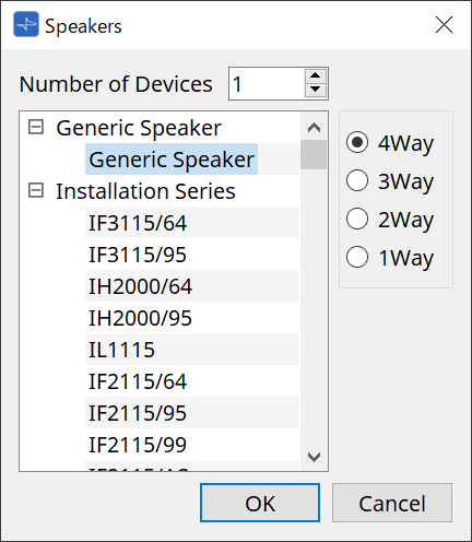
When you connect an amp and speaker, and double click on the speaker, the Speaker Editor is displayed.
The Speaker Editor allows you to control the parameters of the power amplifier from which you are connecting.
For details, refer to "Speaker Editor / Multi Speaker Editor."
18.2.2. Speaker Editor / Multiple Speaker Editor
When a speaker is connected to a PC-series device via a wire, the parameters of the PC-series device’s speaker processor are shown for each individual speaker.
When you double-click a speaker or right-click and choose [Open Speaker Editor] from the context menu, the Speaker Editor opens.
When multiple speakers are selected, you can right-click and choose [Open Multiple Speaker Editor] from the context menu to open the Multiple Speaker Editor.
This is convenient in the following situations.
-
When speakers are connected to multiple PC-series devices, and you want to view each of these speaker processors in a single step.
-
When you want to view the superimposed response curves of the Main and Sub speakers. (Multiple Speaker Editor)
For details on the parameters, refer to "Speaker Processor" component editor of the "ProVisionaire Design Component Guide" .
18.2.3. Properties Area
This area allows you to display and edit device information. The following section explains “Input Source Redundancy”.For other settings, refer to the PC series instruction manual.
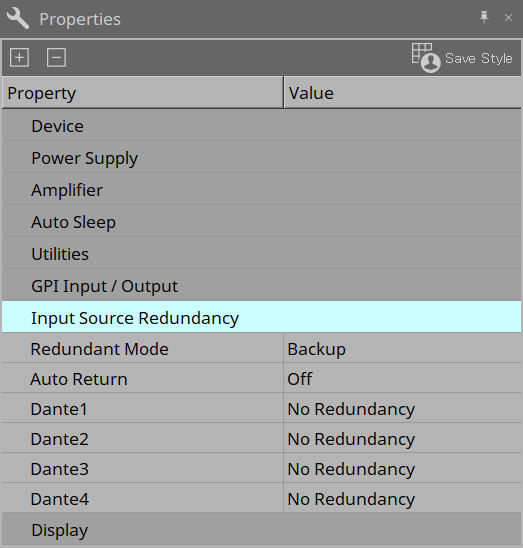
Input Source Redundancy
The PC series has two redundancy modes: "Backup Mode" and "Override Mode".
| Input Source Redundancy is a function that is independent from the Dante network redundancy function. |
-
Redundant Mode
-
Backup
If the input audio on a primary line (Dante 1 to 4) is cut off due to a problem such as an input device failure, the line will automatically switch to the backup line (Dante 13 to 16, Analog 1 to 4). -
Override
When audio input from a backup line (Dante 13 to 16, Analog 1 to 4) is detected, the detected signal will automatically interrupt the audio on the primary line (Dante 1 to 4). This allows for broadcast interruptions, such as high-priority emergency broadcasts and site-wide announcements.In either mode, the backup lines can be set up in two tiers, and the channel combinations are fixed.
PRIMARY SOURCE 2nd SOURCE 3rd SOURCE Dante IN 1
Dante IN 13
Analog IN 1
Dante IN 2
Dante IN 14
Analog IN 2
Dante IN 3
Dante IN 15
Analog IN 3
Dante IN 4
Dante IN 16
Analog IN 4
-
-
Auto Return
-
In Backup Mode
When this option is turned on, the input source will automatically switch back to the primary line when the primary line is restored. -
In Override Mode
When this option is turned on, the input source will automatically switch back to the primary line when the audio from the backup line falls below the threshold.
-
-
Dante 1 to 4
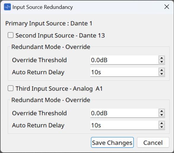
-
Input Source checkbox
Set whether to enable (on) or disable (off) the backup lines at each tier. The backup lines can be set up in two tiers, and the channel combinations are fixed. -
Override Threshold
For Override Mode, set the input level threshold for each channel to determine whether an interrupting input signal is present. -
Auto Return Delay
When Auto Return is turned on in Override Mode, set the time from when the interrupt input signal ends until the line switches back to the primary line.
-
18.3. "Tuning" sheet
The Tuning sheet allows you to set parameters (such as EQ and Delay) for grouped channels collectively.
For the sheet details, please refer to the
"Tuning" sheet
.
18.3.1. Link group editor
This is the parameter setting screen for link groups.
This appears when you double-click a link group on the "Tuning" sheet in which a channel of a PC-series unit is registered, or when you right-click and choose [Open Link Group Editor].
-
[SOLO] button
When online, this is enabled if the tool bar’s [Solo Mode] button is on.
If this is turned on, audio is output only from the channels that are registered to this link group, which is convenient when making final adjustments to the EQ, volume, and delay.
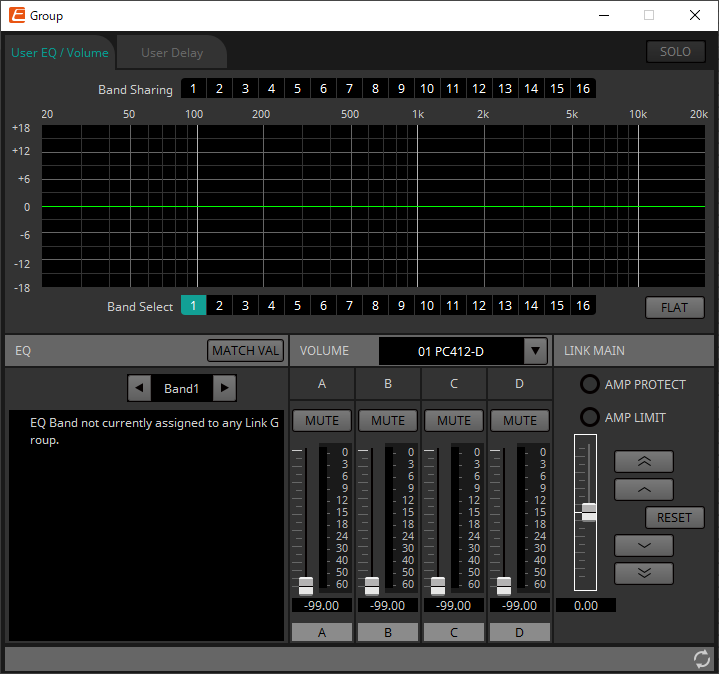
18.3.2. [User EQ/Volume] tab
Here you can make collective adjustments to the User EQ and volume of the channels registered in the group.
Use the Master fader to control the volume.
The "Volume" master fader collectively applies a relative adjustment to the volume of the channels registered in the group.
For details, refer to
"User EQ/User Delay" component editor
.
-
[Band Sharing] buttons
If a channel is registered in multiple groups, click to select the bands owned by each group. An owned band is shown in blue. Bands that are not shown as white numbers on a black background are owned by other groups, and cannot be selected or operated.
Bands that you click and are colored blue are currently owned.
Ownership can be relinquished only by the link group editor that owns that band. -
[MATCHVAL] button
Copies the EQ settings of bands owned by the link group editor to the registered channels. -
LINK MAIN
Applies a relative adjustment to the volumes within the link group. -
[AMP PROTECT] indicator
This will light if the protection function of the PC unit itself is operating. -
[AMP LIMIT] indicator
This will light if the limiter of the PC unit itself is operating.-
Master fader
Applies a relative adjustment to the volumes within the link group. The adjustable range is shown above and below in gray.
When you right-click the fader and choose [Match Values], the members of the link group are set to the same volume value. -
 button
Raises the master fader by 3 dB. -
 button
Raises the master fader by 1 dB. -
[RESET] button
Moves the master fader to the 0 position. -
 button
Lowers the master fader by 1 dB. -
 button
Lowers the master fader by 3 dB.
-
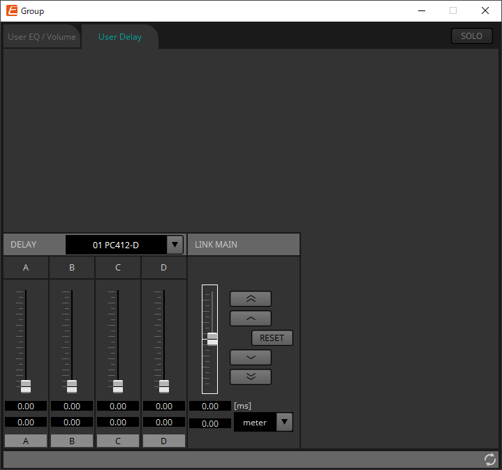
18.3.3. [User Delay] tab
Here you can collectively edit the User Delay of the "User EQ/User Delay" component editor for the linked jacks.
For details, refer to
"User EQ/User Delay" component editor
.
-
LINK MAIN
Here you can apply a relative adjustment to the delay time of the channels of the devices that are registered in this link group.-
Master fader
Applies a relative adjustment to the delay times within the link group. The adjustable range is shown above and below in gray.
When you right-click the fader and choose [Match Values], the members of the link group are set to the same delay time value. -
button
Raises the master fader by 3 ms. -
button
Raises the master fader by 0.3 ms. -
[RESET] button
Moves the master fader to the 0 position. -
button
Lowers the master fader by 0.3 ms. -
button
Lowers the master fader by 3 ms. -
[ms]
Indicates the value of the master fader in ms units. -
[meter]/[feet] list box
Causes the display at left to show units of either meters or feet.
This also switches the display for individual jacks.
-
18.4. Device sheet screen configuration
When the PC series device sheet is opened, the "Presets" area and the "Bird’s Eye view" will be displayed.
When you double-click a component in the device sheet, the component editor opens.

①
Presets area
Multiple parameter settings can be stored as presets.
②
Bird’s Eye view
This shows an overview of the sheet.
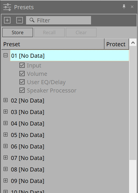
18.5. "Presets" area
In this area, you can store multiple parameter settings as a preset. By recalling the preset, the parameters stored in the preset can be deployed.
The parameters of the preset that is applied are called the "current parameters."
If you want to recall presets for multiple units simultaneously, click the
 button, and make settings in the
"Linked Presets Manager" dialog box
.
button, and make settings in the
"Linked Presets Manager" dialog box
.
-
[STORE] button
This button stores a preset. If you select a preset in which settings have not been stored, the "Store Preset" dialog box appears. -
[RECALL] button
This button recalls a preset. -
[CLEAR] button
This button clears a preset. -
Preset list
This displays a list of the presets. Up to 32 presets can be stored.-
"Preset"
Shows the preset number and name. You can expand this and select the parameters that will be recalled.
If you select a stored preset and double-click this area, you’ll be able to edit the name.
Empty presets are shown with the name [No Data]. -
"Protect"
If you click the lock icon ( ), the icon changes to
 , protecting the preset so that it cannot be edited or cleared.
If you click the icon in the protected state, protection is removed.
-
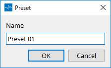
18.5.1. "Store Preset" dialog box
-
[Name]
Input the name of the preset. By default, this will be "Preset + preset number." You cannot enter a blank preset name. -
[OK] button
This stores the preset and closes the dialog box. -
[Cancel] button
This cancels the preset store operation, and closes the dialog box.
18.6. Context Menu
The following describes the contents of the context menus that are displayed when you right-click each area.
18.6.1. "Tuning" sheet
The following context menu appears when you right-click the "Tuning" sheet.
| Menu | Content |
|---|---|
|
[Select All] |
[All Link Groups]
|
|
[Close All Editor Windows] |
Closes all editors. |
|
[Snap to Grid] |
If this is checked, objects are placed in alignment with the grid of the sheet. |
18.6.2. Link group in the "Tuning" sheet
The following context menu appears when you right-click a link group, although certain menu items may be present or absent.
| Menu | Content |
|---|---|
|
[Open Link Group Editor] |
Opens the link group editor. For details on the link group editor, refer to each device. |
|
[Open Amplifier Sheet] |
Opens the device sheet of the selected amp. |
|
[Identify] |
Causes the indicators of the amp to flash for several seconds.
|
|
[Delete] |
If a channel is selected, this deletes the channel from the link group.
|
|
[Bring to Front] |
Moves the link group to the foreground. |
|
[Bring to Back] |
Moves the link group to the background. |
18.6.3. "Project Devices" area
The following context menu appears when you right-click a device or channel in the "Project Devices" area.
| Menu | Content |
|---|---|
|
[Find] |
Places the focus on the link group in which the device or channel is registered. |
|
[Add to Link Group] |
Registers the amp’s channels in a link group. If the speaker is connected to an amp, this registers the channel of the connected amp. |
18.6.4. "Link Groups" area
The following context menu appears when you right-click an object in the "Link Groups" area.
| Menu | Content |
|---|---|
|
[Find] |
If you right-clicked a device, this places the focus on that device in the link group, and opens the link group component editor.
|
|
[Delete] |
If you right-clicked a channel, this deletes the channel from the link group.
|
18.6.5. Device sheet
When you right-click on a device sheet in a location with no object, the following context menu will be displayed.
| Menu | Details |
|---|---|
|
[Close All Editor Windows] |
Closes all editors. |
|
[Debug Mode] |
- |
18.6.6. Components in the device sheet/component editor
When you right-click on any location other than the component’s operator or component, the following context menu will be displayed (some items may be omitted).
| Menu | Details |
|---|---|
|
[Open Component Editor] |
Opens the component editor. |
|
[Copy] |
Copies the component editor’s parameter settings. |
|
[Paste Parameters] |
Reflects the component editor’s parameter settings that have been copied. |
18.6.7. "Presets" area
When you right-click on a preset, the following context menu will be displayed.
| Menu | Details |
|---|---|
|
[All On] |
Checks all of the checkboxes that are subject to recall. |
|
[All Off] |
Unchecks all of the checkboxes that are subject to recall. |
18.7. Alert list
The alerts generated by PC-series units, and their significance and the appropriate actions, are listed below.
A single alert is shown when the event occurs. A continuing alert is shown when the event occurs and when it ends.
If the problem is not solved, please contact a Yamaha service center listed at the end of the device’s operating manual.
| Number | Message | Severity | Content | Action | Single/Continuing |
|---|---|---|---|---|---|
|
05 |
Amplifier Output Muting |
Error |
The protection function operated to mute the amp output. |
Take action to clear the protection function that was the cause.
|
Continuing |
|
12 |
Mains Voltage Over 276[V] |
Error |
(at startup) The amp cannot start up because the power supply voltage exceeded the allowable operating voltage. |
Connect a stable power supply that is within the power supply requirements. |
Single |
|
The amp stopped because the power supply voltage exceeded the allowable operating voltage. |
Continuing |
||||
|
13 |
Power Supply Output Voltage |
Fault |
(at startup) The amp cannot start up because there is an abnormality in the output voltage of the power supply circuit. |
It might be that the unit has malfunctioned.
|
Single |
|
The amp was stopped because an abnormality occurred in the output voltage of the power supply circuit. |
Continuing |
||||
|
14 |
Power Supply Over-temperature |
Error |
(at startup) The amp cannot start up because the power supply circuit is too hot. |
- Lower the temperature before use.
|
Single |
|
The amp was stopped because the power supply circuit became abnormally hot. |
Continuing |
||||
|
21 |
Amplifier Ch.* DC Output |
Fault |
(at startup) The amp cannot start up because there is an abnormality in the amp output. |
It might be that the unit has malfunctioned.
|
Single |
|
The amp was stopped because there is an abnormality in the amp output of the corresponding channel. |
Continuing |
||||
|
22 |
Amplifier Ch.* Overcurrent |
Error |
The output was muted because excessive current flowed to the amp of the corresponding channel. |
- Reduce the output volume so that the current value does not become excessive.
|
Continuing |
|
23 |
Amplifier Ch.* Overtemp Level 1 |
Error |
Because the amp temperature of the corresponding channel exceeded level 1, the fan rotation speed was raised and the limiter was applied to the output. |
- Reduce the output volume so that the temperature does not become excessive.
|
Continuing |
|
24 |
Amplifier Ch.* Overtemp Level 2 |
Error |
Because the amp temperature of the corresponding channel exceeded level 2, the fan rotation speed was raised and the limiter was applied to the output. |
Continuing |
|
|
25 |
Amplifier Ch.* Overtemp Level 3 |
Error |
Because the amp temperature of the corresponding channel exceeded level 3, the fan rotation speed was raised to the maximum and the output was muted. |
Continuing |
|
|
26 |
Ch.* High Load |
Warning |
The impedance value of the corresponding channel monitored by the Load Monitoring function is higher than the specified value. |
- Check that there is no abnormality in the speaker or cable.
|
Continuing |
|
27 |
Ch.* Low Load |
Warning |
The impedance value of the corresponding channel monitored by the Load Monitoring function is lower than the specified value. |
Continuing |
|
|
31 |
Fan * Error |
Fault |
The fan of the corresponding number has stopped rotating. |
It might be that the unit has malfunctioned.
|
Continuing |
|
42 |
Input D* Change To 2nd |
Warning |
The Input Source Redundancy function has switched the audio to the second priority circuit. |
Check whether the main audio circuit (Dante) has malfunctioned.
|
Single |
|
43 |
Input D* Change To 3rd |
Warning |
The Input Source Redundancy function has switched the audio to the third priority circuit. |
Check whether the main or the second priority audio circuit (Dante) has malfunctioned.
|
Single |
|
61 |
Dante Module Failed |
Fault |
The internal Dante module is not working correctly. |
It might be that the unit has malfunctioned.
|
Continuing |
|
63 |
Firmware Versions Mismatch |
Error |
The version of this unit’s firmware is not compatible with the version of the Dante firmware. |
The updater provided on the web contains the firmware for this unit and the Dante firmware as a set. Update both. |
Single |
|
64 |
Dante Is Not Working By Giga Bit |
Error |
A device that does not support gigabit Ethernet is connected.
|
If you want to transmit audio via Dante, use devices that support gigabit Ethernet. |
Continuing |
|
65 |
Dante Is Working At Secondary |
Warning |
In Redundant mode, Dante audio communication is occurring on the Secondary circuit.
|
Check whether the primary circuit may have malfunctioned. |
Continuing |
|
66 |
Error Occurred At Secondary Port |
Warning |
In Redundant mode, the Dante Primary circuit is operating correctly, but the Secondary circuit is not connected.
|
If connection of the Secondary circuit is needed, check whether it may have malfunctioned. |
Continuing |
|
67 |
Wrong Word Clock |
Warning |
A problem was detected in the word clock. |
- In Dante Controller, correctly set the word clock of the entire system.
|
Continuing |
|
69 |
Dante Port Is Not Connected |
Warning |
In Redundant mode, the Dante Primary circuit is operating correctly, but the Secondary circuit is not connected.
|
Make sure that the Dante circuit is correctly connected. |
Continuing |
18.8. Component editors
The component editor allows you to set and adjust each component of the selected device.
When you double-click a component in the device sheet, the component editor opens.
This section describes the PC series component editor, and the dialogs and windows that are closely associated with the components. For details about other components, refer to the
"ProVisionaire Design Component Guide"
.

| Number | Component name | Details | Link |
|---|---|---|---|
|
① |
Power |
This function switches the device’s power supply and displays the electrical current value for the main unit. |
|
|
② |
DANTE IN |
Displays the settings related to the [Dante] terminal input and the level of the audio signal being input. |
|
|
③ |
ANALOG IN |
Displays the settings related to the [INPUT] terminal input and the level of the audio signal being input. |
|
|
④ |
Redundancy |
Sets the input source and Override/Backup operation at a per-channel level. |
--- |
|
⑤ |
Input |
Adjusts the levels of input channels and displays their statuses. |
|
|
⑥ |
Matrix Mixer |
Adjusts the group balance for each output bus. |
|
|
⑦ |
Matrix Out |
Adjusts the level from the matrix mixer to the router and Dante outputs. |
--- |
|
⑧ |
Router |
Assigns matrix mixer output to output channels. |
|
|
⑨ |
Volume |
Adjusts the level of the output channel. |
--- |
|
⑩ |
User EQ/Delay |
Sets the output channel EQ/delay. |
|
|
⑪ |
Speaker Processor |
Sets the output channel speaker processor. |
|
|
⑫ |
Amplifier |
Set the amp output mode and impedance detector. |
|
|
⑬ |
DANTE OUT |
Shows the Dante output level. |
--- |
|
⑭ |
SPEAKER OUT |
Displays the speaker output terminal’s output voltage and output current. |
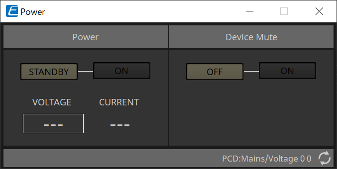
18.8.1. "Power" component editor
Switches the power of the device, and indicates the electrical current value of the unit.
This is available only when online.
-
Power
-
[STANDBY]/[ON] buttons
Switch the power between standby/on. -
[VOLTAGE]
Indicates the voltage value of the power supply input. -
[CURRENT]
Indicates the electrical current value of the device.
-
-
Device Mute [OFF]/[ON] buttons
Switch the device’s Device Mute on/off.
If this is on, the speaker output is muted for all channels of the amp.
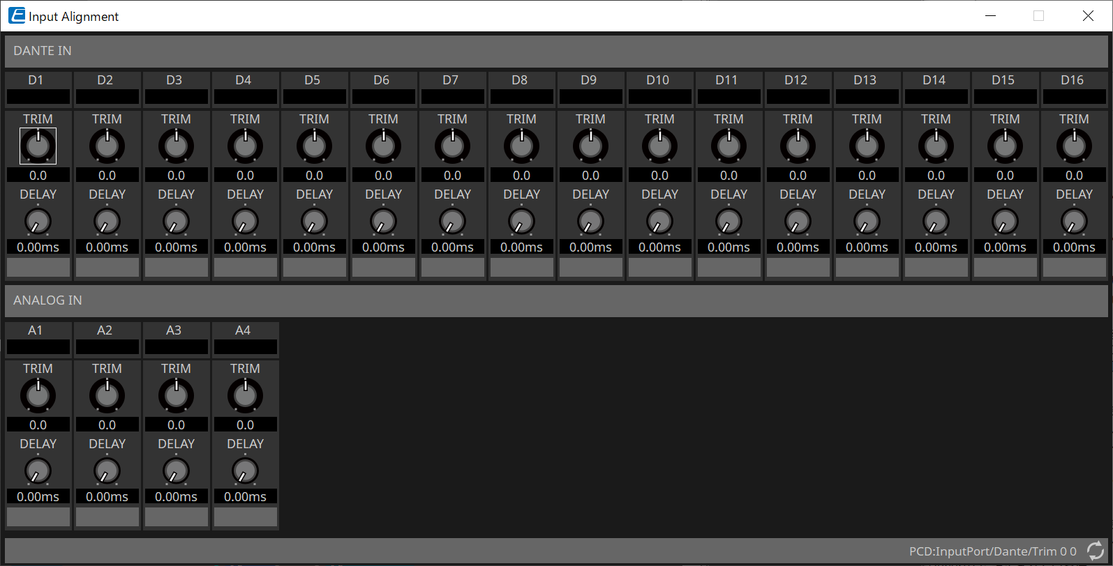
18.8.2. "Input Alignment" component editor
This appears when you double-click the "DANTE IN" component or the "ANALOG IN" component.
Here you can make settings for the input jacks, and view the levels of the audio signals that are being input.
-
Input level
Indicates the level after it is compensated by TRIM and DELAY. -
[TRIM] knob
Compensates for level differences between input jacks. -
[DELAY] knob
Compensates for latency differences between input jacks. -
Channel name
Shows or edits the input jack name.
18.8.3. Input Component Editor
This editor allows you to adjust input channels (level, MUTE, phase) and display their statuses.
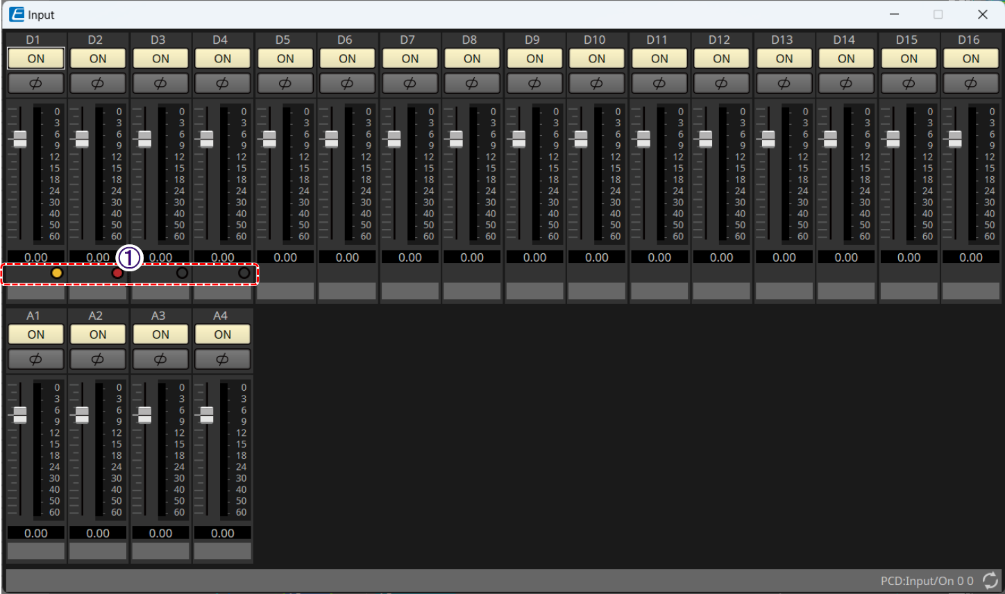
① Input Redundancy Status Indicator
If the Input Source Redundancy function is enabled, the current input line (Dante 1 to 4 only) is indicated.
![]() Off: Primary line
Off: Primary line
![]() Lit (orange): 2nd SOURCE line
Lit (orange): 2nd SOURCE line
![]() Lit (red): 3rd SOURCE line
Lit (red): 3rd SOURCE line
For details about Input Source Redundancy, refer to "Input Source Redundancy" .
18.8.4. "User EQ/User Delay" component editor
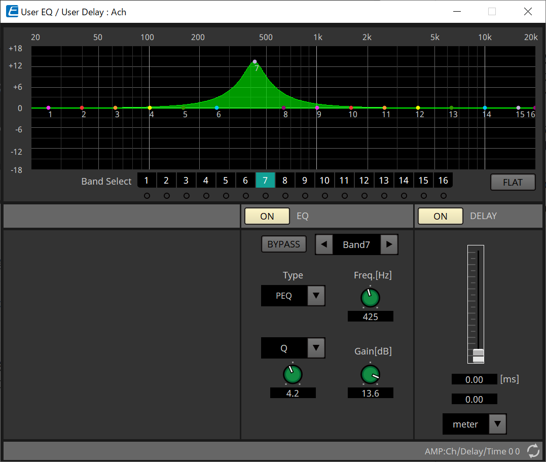
-
EQ graph
Shows a graph of the EQ effect.
You can drag a control point to edit the parameters. -
[Band Select] buttons
If a button is selected, the current value is shown in "EQ," below. For bands whose "EQ" [BYPASS] button is on, the indicator below that [Band Select] button is lit.
For details about other parameters, refer to the "ProVisionaire Design Component Guide" .
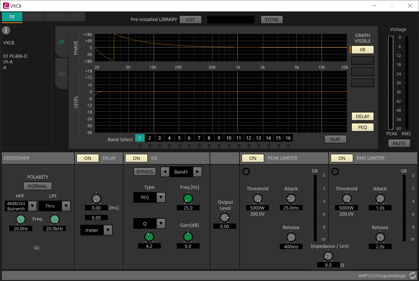
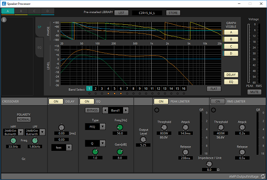
18.8.5. "Speaker Processor" component editor
「PEAK LIMITER」/「RMS LIMITER」
This is not shown if the corresponding jack is set as a high-impedance connection such as 70V or 100V.
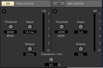
-
[ON] button
Turns the limiter on/off. If the button is off, the limiter will be bypassed. -
Gain Reduction indicator
This will light when the threshold value is exceeded. -
[Threshold] knob
This specifies the threshold value at which the limiter applies, in terms of output power (W). -
[Attack] knob
Specifies the speed at which the limiter will take effect. -
[Release] knob
Specifies the speed at which the limiter will release. -
"GR" meter
Indicates the amount of gain reduction. -
[Impedance / Unit] knob
Specifies the nominal impedance of the speaker.
Even when connecting multiple speakers in parallel, specify this as the impedance of one unit.
For other information, refer to the "ProVisionaire Design Component Guide" .
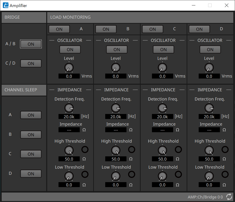
18.8.6. "Amplifier" component editor
-
BRIDGE [ON] button
If this is enabled, the amp will be in BRIDGE output mode.
In BRIDGE mode, adjacent odd-numbered and even-numbered channels are bridge-connected to operate as a high-power amp. -
CHANNEL SLEEP [ON] button
If this is enabled, the amp of that channel will sleep. By putting unused channels to sleep, you can conserve electrical power and reduce excessively high temperatures.
This is different than the Auto Sleep setting in the "Properties" area of the "Project" sheet. -
"LOAD MONITORING"
Here you can make settings for monitoring the speaker output impedance in order to determine whether the output has been interrupted by an electrical short, breakage, or speaker malfunction. By outputting a pilot tone, the impedance can be detected in a stable manner without relying on the audio signal output.
This is not shown for channels that are specified as a Hi-Z connection.-
[ON] button
Switches LOAD MONITORING on/off. -
OSCILLATOR [ON] button
Specifies whether a pilot tone is output.
A pilot tone from an external input can also be used to detect the impedance. -
OSCILLATOR [Level] knob
Specifies the output level of the pilot tone. -
IMPEDANCE [Detection Freq.] knob
Specifies the frequency for which impedance is detected. The [Impedance] field below shows the measured impedance. -
IMPEDANCE [High Threshold] knob/indicator
Specifies the upper threshold of impedance that is measured. If the specified value is exceeded, it is determined that the speaker has malfunctioned, and the indicator will light.
If the specified value is exceeded, it might be that the connection is open, such as due to a broken cable. -
IMPEDANCE [Low Threshold] knob/indicator
Specifies the lower threshold of impedance that is measured. If the measurement drops below the specified value, it is determined that the speaker has malfunctioned, and the indicator will light.
If the measurement drops below the specified value, it might be that the resistance has dropped due to a shorted coil, etc.
-
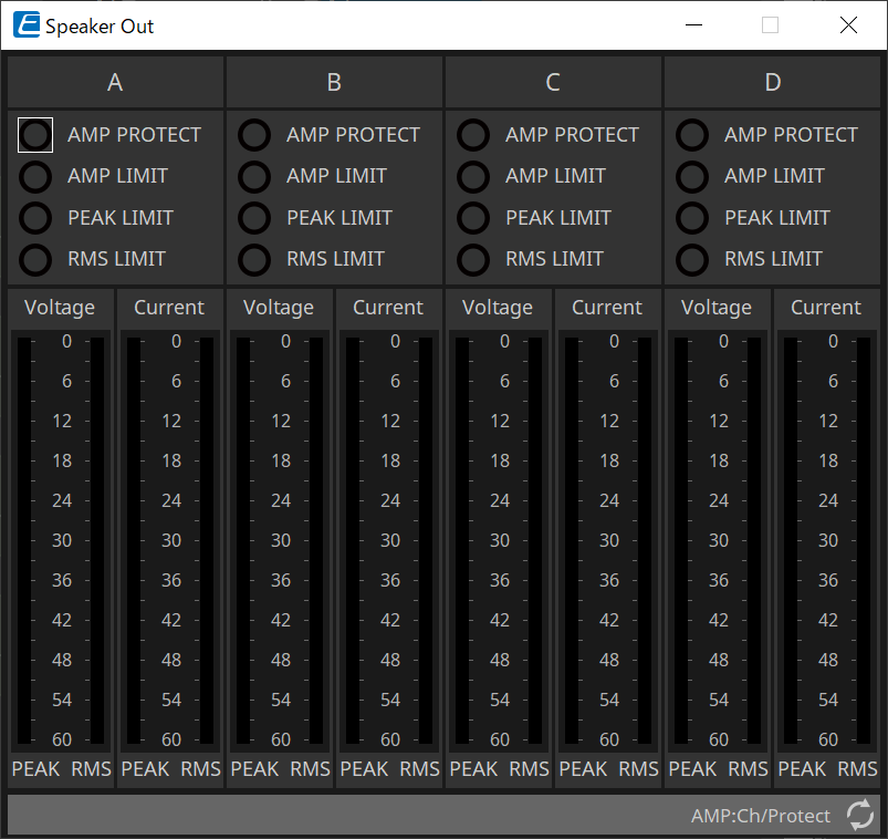
18.8.7. "Speaker Out" component editor
This shows the speaker output jack’s output voltage and output current.
-
[AMP PROTECT] indicator
This will light if the protection function of the PC unit itself is operating. -
[AMP LIMIT] indicator
This will light if the limiter of the PC unit itself is operating. -
[PEAK LIMIT] indicator
This is lit if the peak limiter within the speaker processor of the PC unit is operating. -
[RMS LIMIT] indicator
This is lit if the RMS limiter within the speaker processor of the PC unit is operating. -
[Voltage] meter
Shows the output voltage as Peak and RMS. -
[Current] meter
Shows the output current as Peak and RMS.