"Project" sheet
7. "Project" sheet
7.1
"Project" sheet
7.2
"Devices" area
7.3
"Network" area
7.4
"Properties" area
7.5
Placing devices
7.6
Selecting multiple objects
7.7
Connecting ports
7.8
Duplicating devices
7.9
"Group" Editor
When you open the "Project" sheet, the "Devices" area, "Network" area, "Project" sheet, "Properties" area, and "Bird’s Eye" view appear.
"Bird’s Eye" view shows the entirety of the "Project" sheet.
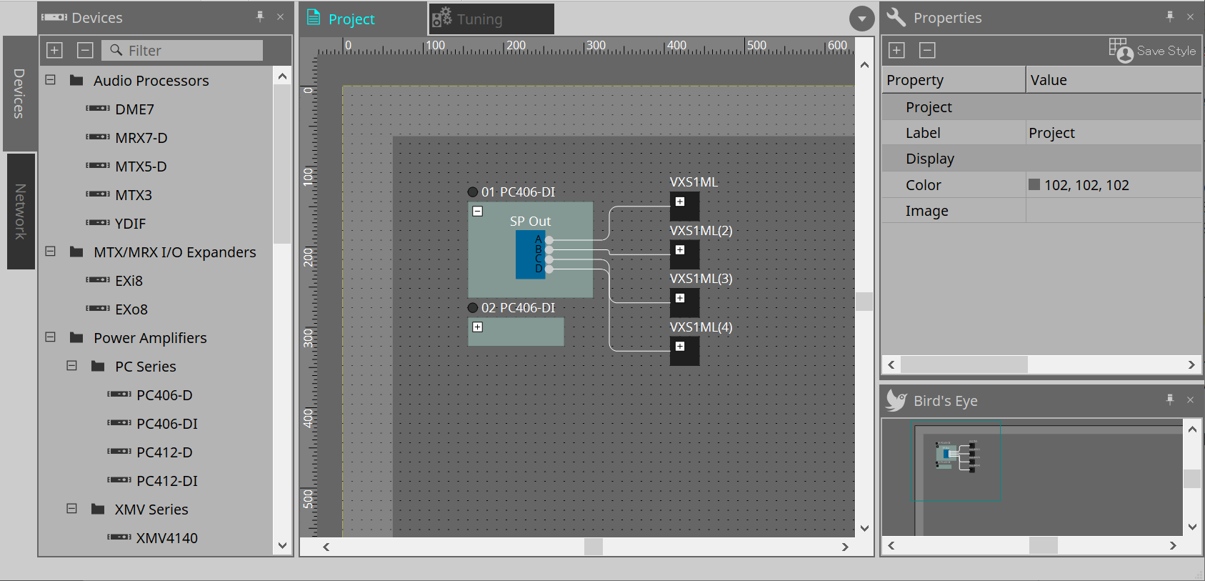
7.1. "Project" sheet
You can place devices in this sheet. The devices placed here are registered in the project.
Basic settings for a registered device are made in the "Properties" area.
7.2. "Devices" area
To place a device in the "Project" sheet as a virtual device, drag and drop the device from this area.
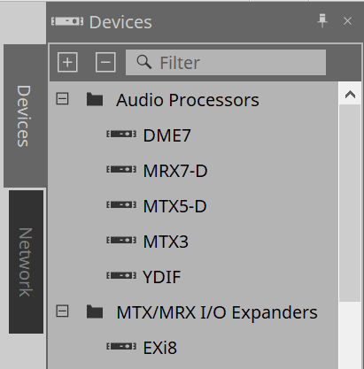
| For more information on the YDIF, refer to the section for the "YDIF" . |
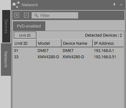
7.3. "Network" area
The devices that are on the same network as the computer are detected and shown here.
A device shown here can be registered in the project by dragging and dropping it into the "Project" sheet.
When you click the [Unit ID] button, the "Change Unit ID" dialog box appears.
RM-CG / RM-TT
To control these devices, you must log in to ProVisionaire Design.
If the initial password has not been specified, the
![]() icon will appear. If the initial password has been specified but you have not logged in, the
icon will appear. If the initial password has been specified but you have not logged in, the
![]() icon will appear.
icon will appear.
You can control these devices via “RM Settings,” which you can access from the context menu or [System] menu.
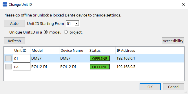
7.3.1. "Change Unit ID" dialog box
In this dialog box you can change the UNIT ID of the device. When you change the UNIT ID, that device will restart, so it will temporarily disappear from the "Network" area.
You can’t change the UNIT ID of a device that is in the online state.
Applicable devices: DME10/DME7, PC series, RM-CG, RM-TT, VXL1-16P, DZR/DXS-XLF series (Dante models only)
| This operation does not apply to the MTX series or XMV series units. Use the dip switches on the rear panel to set the Unit ID. |
-
[Auto] button
Automatically assigns a UNIT ID to each device, starting with the number selected in the [Unit ID Starting From] list box. -
[Unique Unit ID in a model/project] option buttons
Specify whether the UNIT ID assignments that are made when you press the [Auto] button are unique for each model or unique for each project. -
[Refresh] button
Updates the device list located below the button. -
[Accessibility] button
Opens a supplementary "Unit ID" window that lets you change the UNIT ID of the currently selected device. The "Unit ID" window also opens when you right-click somewhere other than the Identify button or the [Unit ID] text box in the device list below. -
Device list
The devices that are on the same network as the computer are detected and shown here.-
Identify button
When you press this button located at the left of the UNIT ID, the indicators of the corresponding device will flash for several seconds. -
[Unit ID] text box
Specifies the UNIT ID of the corresponding device. -
[Model]/[Device Name]/[Status]/[IP Address]
Show information for the device. You can click to sort the list.
-
■ "Unit ID" dialog box
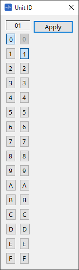
Click the buttons to display the Unit ID at the top.
You can change the Unit ID for one or more devices.
| If you select "0" for the higher digit while the lower digit has been set to "0," the higher digit will automatically be set to "1." |
-
[Apply] button
Applies the Unit ID to the currently-selected device.
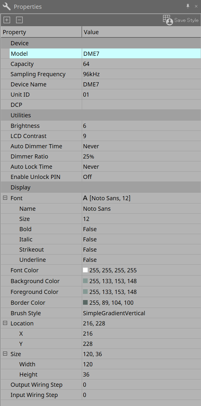
7.4. "Properties" area
Here you can view and edit information about the sheet or object.
For details on items related to the settings of a device, or on items that appear in the dialog box when you click, refer to the section on each device.
-
[Save Style] button
Click the [Save Style] button to save the information displayed in the "Properties" area to the computer as the default values. These values will be applied to other newly-created projects.
Components, ports, wires, and the design sheet are saved.
Items specified in the "Properties" area can be saved as a user style, so that the next time you place a new component or connect wires, they will be placed with the same appearance as was saved in the style.
If you want to use the same user style on another computer, execute one of the following procedures.-
Use [File] menu → [Export Style] to save the user style as a file; then use [File] menu → [Import Style] on the other computer to load the file.
-
Use [File] menu → [Save with Style] to create a project file that includes the user style; then after loading the file on the other computer, use [File] menu → [Import Style from Project File] to load it.
-
-
Device
-
Model
Indicates the model name. -
Device Name
Indicates the User Defined Name of the target device. Double-click this field to edit the name. -
Unit ID
Indicates the Unit ID for the device. You cannot edit this field while the device is online.
-
-
Display
-
Output Wiring Step
Set length of output side wiring step. If equal spacing is desired, please set "Wire Routing" to Automatic and set "Auto Block Avoidance" to False. -
Input Wiring Step
Set length of input side wiring step. If equal spacing is desired, please set "Wire Routing" to Automatic and set "Auto Block Avoidance" to False.
-
-
Object
When the port of a device or component on the sheet is selected, click the that appears when you click on Label to open the
Port Label dialog
.
that appears when you click on Label to open the
Port Label dialog
.
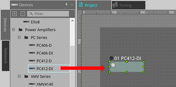
7.5. Placing devices
Here we explain how to place devices on the "Project" sheet.
|
-
Drag and drop a device from the "Devices" area into the "Project" sheet.
You can select the number of devices and the UNIT ID. The UNIT ID can be changed in the "Properties" area.
-
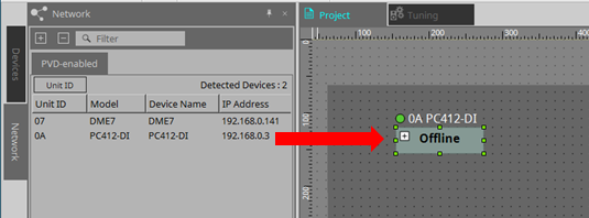
Connect the computer to the network of devices, and then drag and drop a device from the "Network" area into the "Project" sheet.
If a device that you understand to be connected is not shown in the "Network" area, check that the device actually is connected to the network, and that it is powered-on.
Speakers are not shown in the "Network" area.
|
7.6. Selecting multiple objects
Here we explain how to select multiple objects placed in the "Project" sheet.
-
Use the mouse cursor to completely enclose objects
By dragging the mouse cursor, you can select the objects that are completely enclosed in the rectangular area on the sheet. -
Hold down < Ctrl > and use the mouse cursor to completely or partially enclose objects
By dragging the mouse cursor while you hold down < Ctrl >, you can select the objects that are completely or partially enclosed in the rectangular area on the sheet.
To select objects inside a device, start dragging inside that device. Only the objects inside that device are subject to selection.
| If the selection encloses a Device Group, and the point at which you start dragging is on the sheet, then the objects on the sheet are selected. If the point at which you start dragging is on a Device Group, then objects inside that Device Group are selected. |
-
Hold down < Ctrl > and click objects
To select multiple objects, hold down < Ctrl > and click each target that you want to select.
If you hold down < Ctrl > and click an object that is already selected, the selection is cleared.
7.7. Connecting ports
Here we explain how to make connections between ports of devices by creating a wire between the ports.
-
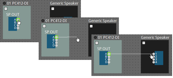
Make one connection at a time
Drag one output port to the input port of the destination device.
-
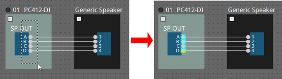
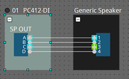
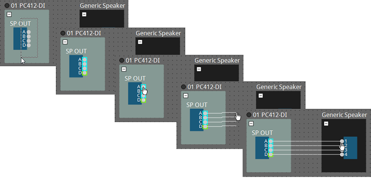
Make multiple connections at a time
Select multiple output ports, and drag one of these ports to an input port of the destination device.
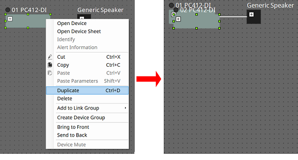
7.8. Duplicating devices
Here we explain how to duplicate devices together with their parameters.
-
Right-click an object and choose [Duplicate]
A duplicate, overlapping object is created. If multiple objects with their wires are selected when you choose [Duplicate], the objects are duplicated together with their wires.
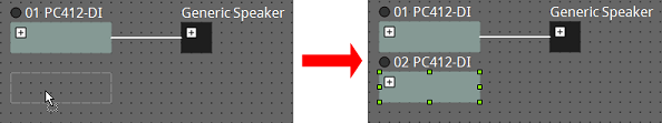
-
Drag and drop an object while holding down < Ctrl >
A duplicate is created where you drop the object.
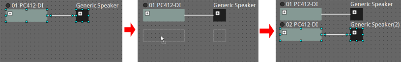
-
Drag and drop objects with their wires while holding down < Ctrl >
Duplicates of the components together with their wires are created where you drop the component.
7.9. "Group" Editor
The devices in a device group can be powered on/off or muted in a single step.
When you double-click a device group or right-click and choose [Open Group Editor] from the context menu, the "Group Editor" opens.
This is available only when online.
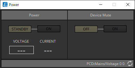
-
"Power" area
Switches the power of the devices in the device group to standby or on at once. -
"Device Mute" area
Enables/disables the mute setting of the devices in the device group at once.