Dialog boxes
10. Dialog boxes
10.1
Startup dialog box
10.2
"Go Online- From Devices" dialog box
10.3
"Protect File" dialog box
10.4
"Project Information" dialog box
10.5
"Print" dialog box
10.6
"File Storage" dialog box
10.7
"Network Setup" dialog box
10.8
"IP Settings" dialog box
10.9
"IP Address" dialog box
10.10
"Auto-Assign IP Addresses" dialog box
10.11
"Match Devices by IP Address" dialog box
10.12
"Device Information" dialog box
10.13
"Update Firmware" dialog box
10.14
"Initialize" dialog box
10.15
"Word Clock" dialog box
10.16
"Protect Devices" dialog box
10.17
"Clock" dialog box
10.18
"Daylight Saving Time" dialog box
10.19
"GPI Calibration" dialog box
10.20
"Get Log from Devices" dialog box
10.21
"RM Series Settings" > "Sign up" dialog box
10.22
"RM Series Settings" > "Login" dialog box
10.23
"RM Series Settings" > "Password Settings" dialog box
10.24
"RM Series Settings" > "Enable SCP remote control access" dialog box
10.25
"Linked Presets Manager" dialog box
10.26
"Store Linked Preset" dialog box
10.27
Port Label Dialog
This chapter explains the dialog boxes and windows that you can open from the menu bar or tool bar.
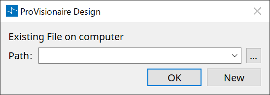
10.1. Startup dialog box
This appears when ProVisionaire Design starts.
-
[Path] pulldown menu
Lets you view and select a recently saved project file. -
[…] button
Opens the "Select File" dialog box. Select the project file that you want to load. -
[OK] button
Loads the project file that is shown in the [Path] pulldown menu. -
[New] button
Starts a new project.
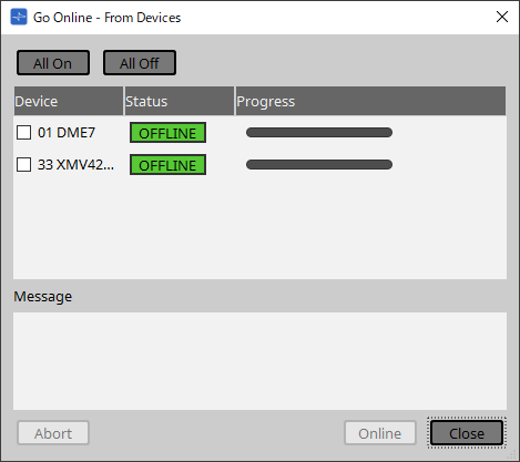
10.2. "Go Online- From Devices" dialog box
To open this dialog box, click [Go Online - From Devices] from the [File] menu on the menu bar.
For more information on the "Go Online - From Devices" dialog box, refer to the “Online and synchronization” chapter.
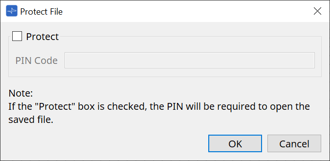
10.3. "Protect File" dialog box
To open this dialog box, click [Protect File] from the [File] menu on the menu bar.
In ProVisionaire Design, you can specify a PIN code (secret number) in the project file for security.
-
[Protect] check box
If this check box is selected, the "Security" dialog box will appear when the project file starts.
If this check box is cleared, all users will be able to open the project file. -
[PIN Code]
If the [Protect] check box is selected, enter the PIN code (secret pass code). (The code should be six alphanumeric characters drawn from numbers 0 through 9 and letters a, b, c, d, e, and f. The code is not case sensitive.)
| If you forget the PIN code, you will be unable to open the corresponding project file. |
-
[OK] button
Updates the settings and closes the dialog box. -
[Cancel] button
Closes the dialog box without updating the settings.
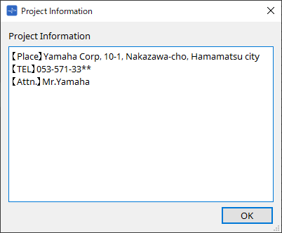
10.4. "Project Information" dialog box
To open this dialog box, click [Project Information] from the [File] menu on the menu bar.
Allows you to include a memo in the project file to record property information or contact information.
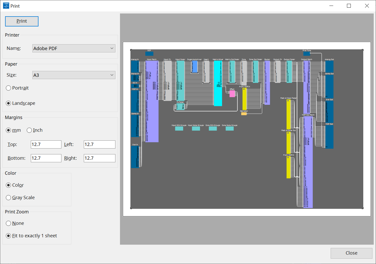
10.5. "Print" dialog box
To open this dialog box, click [Print] from the [File] menu on the menu bar.
Here you can make settings related to printing a sheet, specify the size of paper shown on the sheet, and see a print preview.
-
[Print] button
Click this to open the Windows "Print" dialog box. -
Printer
-
[Name] list box
Specifies the printer to use.
-
-
Paper
-
[Size] list box
Specifies the size of the paper. If the [View] menu item [Print Area] has a check mark, the size of paper shown on the design sheet follows this setting. -
[Portrait]/[Landscape] option buttons
Specify the orientation of the paper. The orientation of the paper shown on the design sheet follows this setting.
-
-
Margins
-
[mm]/[Inch] option buttons
Specify the units for the top, bottom, left, and right margins. -
[Top]/[Bottom]/[Left]/[Right] text boxes
Specify the top, bottom, left, and right margins.
-
-
Color
-
[Color]/[Gray Scale] option buttons
Specify whether to print in color or in gray scale.
-
-
Print Zoom
-
[None]/[Fit on one page] option buttons
Specify either that the printed content will be the region within the paper shown on the design sheet, or that the entire sheet will be reduced in size to fit on a single page.
-
-
Preview area
Shows a print preview.
10.6. "File Storage" dialog box
To open this dialog box, click [File Storage] from the [File] menu on the menu bar. You can save the project file from ProVisionaire Design to the DME unit.
Only one project file can be saved to each DME unit.
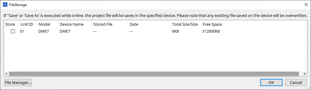
All DME units that are detected by ProVisionaire Design will be listed.
-
[Store] check box
Enables you to select a DME unit to which you wish to save the project file. You can select multiple DME units.
If you execute the Save, Save As, or Save with Style command while ProVisionaire Design and the devices are connected online, the project file will be automatically transferred and saved not only to the computer but also to currently-selected multiple DME units.
| Please be aware that at this time, the files that are currently stored on the devices will be overwritten. |
-
Unit ID / Model / Device Name
These columns indicate the device Unit ID, device model name, and device name.
To change the device name, use the [Device Name] field in the “Properties” area of the “Project” sheet. -
Stored File
If any file is stored on the device, this field will indicate the name of the file.
If no file is stored on the device, this field will be empty. If no device is detected, this field will indicate “---.” -
Date
If a file has already been stored on the device, this field will indicate the date and time at which the file was updated.
If no file is stored on the device, this field will be empty. If no device is detected, this field will indicate “---.” -
Total Size/Size
For a device, this field indicates the size of the save destination. For a file, this field indicates the file size.
If no device is detected, this field will indicate “---.” -
Free Space
This field applies only to the device, and indicates the available space at the save destination.
If no device is detected, this field will indicate “---.” -
[File Manager] button
Click this button to open the [File Manager] dialog box.
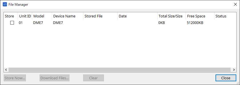
10.6.1. [File Manager] dialog box
To open this dialog box, click the [File Manager] button in the [File Storage] dialog box. You can save any project file to the DME.
As the save destination, you can specify any DME unit that ProVisionaire Design detects on the network.
-
[Store] check box
Enables you to select the save destination(s) when the “Store Now” command is executed. You can select multiple destinations. -
Status
Indicates the progress status of the save operation when the “Store Now” command is executed. -
[Store Now] button
Transfers the project file to the device(s) for which the check box has been marked. -
[Download Files] button
Downloads the file from a device for which the check box has been marked. -
[Clear] button
Deletes a file that is stored on a device for which the check box has been marked.
10.7. "Network Setup" dialog box
To open this dialog box, click [Network Setup] from the [System] menu on the menu bar.
Here you can select the computer’s network interface card (subsequently called the "network card") used for communicating with devices.
You can also change the IP address of the network card.
|
If you’re not using a DHCP server, fix the IP address of your computer’s network card. We recommend the following settings.
IP address: 192.168.0.253 Subnet mask: 255.255.255.0 |
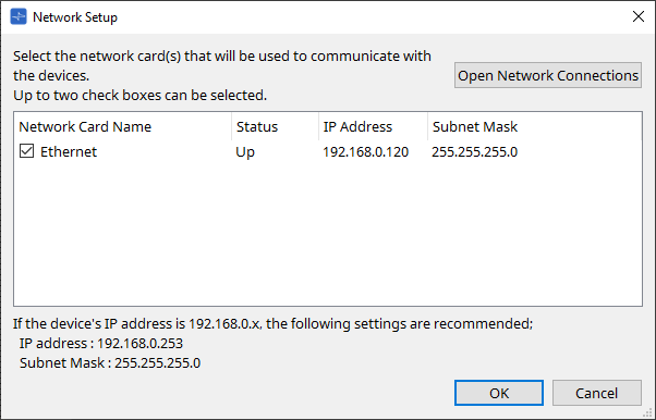
If the computer is not connected to the network, click the [Cancel] button to close the dialog box.
-
Network Card Name
Shows the name of the network card. -
Status
Shows the status of the network card (Up or Down). -
IP Address and Subnet Mask
Indicates the IP address and subnet mask that are assigned to the network card.
Select a network card of the same subnet as the devices. -
[Open Network Connections] button
Opens the control panel "Network Connections." Use this when you want to change the IP address of the network card. -
[OK] button
Updates the settings and closes the dialog box. -
[Cancel] button
Closes the dialog box without updating the settings.
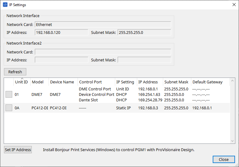
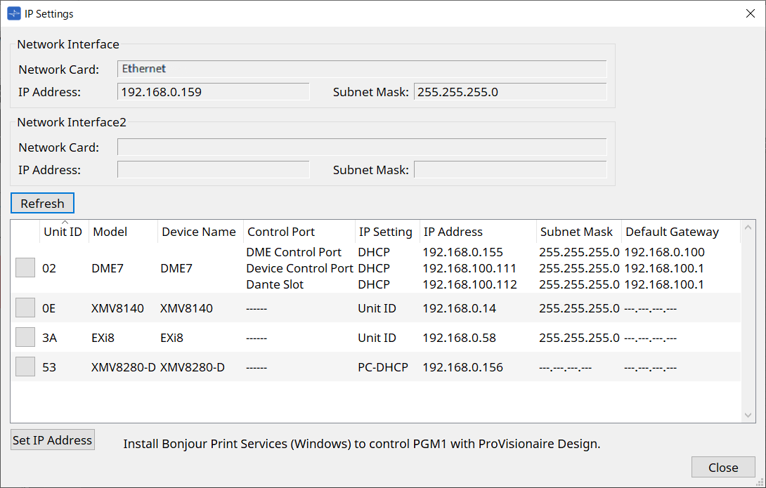
10.8. "IP Settings" dialog box
To open this dialog box, click [IP Settings] from the [System] menu on the menu bar.
Lists the devices found on the network, allowing you to change their IP address.
-
Network Interface
Shows the name/IP address/subnet mask of the network card currently selected in the "Network Setup" dialog box. -
[Refresh] button
Searches again for devices on the network. -
Device list
-
Identify button
When you press this button located at the left of the UNIT ID, the indicators of the corresponding device will flash for several seconds. -
Unit ID / Model / Device Name
These columns indicate the device Unit ID, device model name, and device name. If there is a UNIT ID conflict, an indication is shown.
To change the device name, use the [Device Name] field in the “Properties” area of the “Project” sheet. -
Control Port
Indicates the port name if multiple control ports exist. -
IP Settings
Indicates the IP setting type. -
IP Address/MAC Address/Subnet Mask/Default Gateway
Indicates the IP address, MAC address, subnet mask, and default gateway that are specified for the device.
-
-
[Set IP Address] button
Opens the "IP Address" dialog box . -
[Close] button
Closes the dialog box.
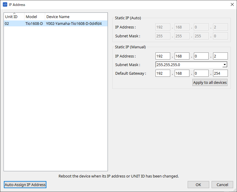
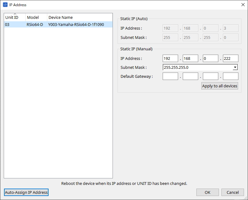
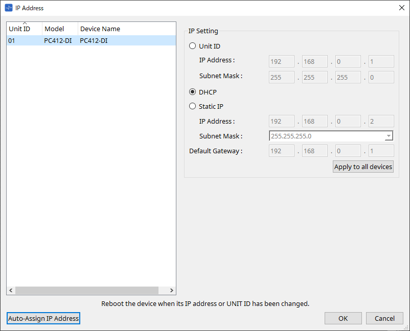
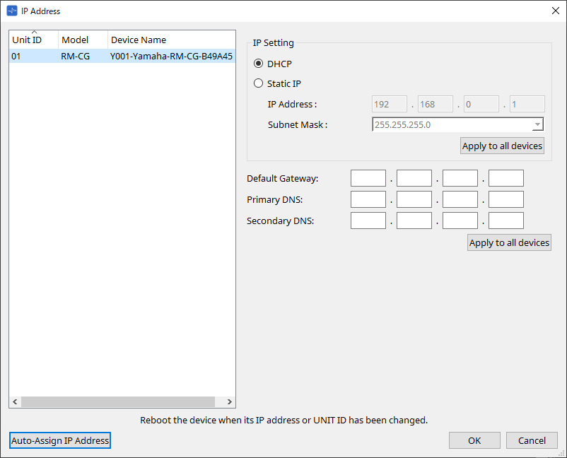
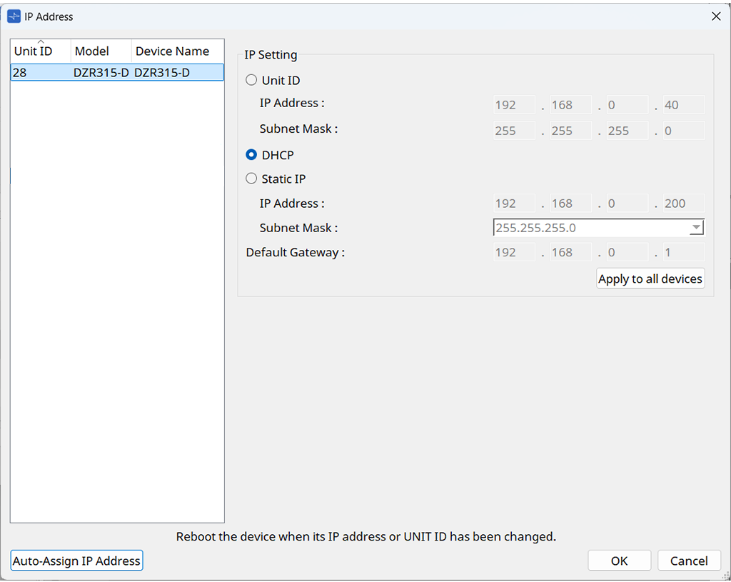
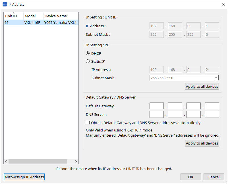
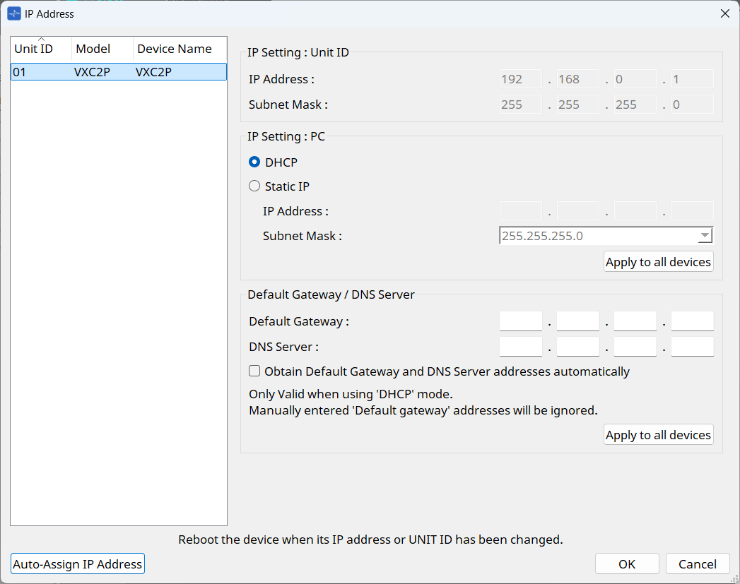
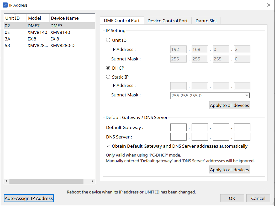
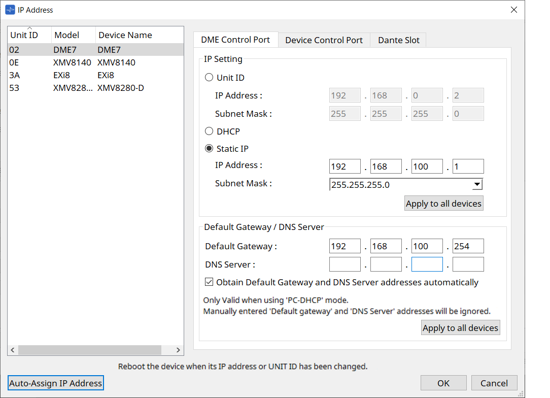
10.9. "IP Address" dialog box
To open this dialog box, click the [Set IP Address] button in the [IP Settings] dialog box.
Here you can set the device’s IP settings. Set this so that there is no conflict between devices.
| Editing is not possible while online. |
In order to use ProVisionaire Design to control devices of differing subnets, it is necessary to operate the devices using fixed IP addresses. For details, refer to
"Settings for controlling devices across subnets"
.
■ For the DME10/7
Specify the parameters on the three tabs: DME Control Port 1, DME Control Port 2, and Dante Slot.
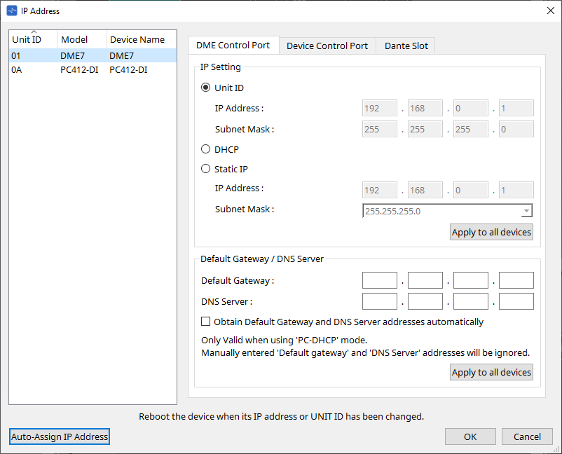
● DME Control Port1 and DME Control Port2 tabs
Set the IP address when a controller such as ProVisionaire Design controls the DME, or when the DME controls other devices.
DME Control Port1 tab
Use this tab for the control via the Network terminal.
DME Control Port2 tab
Use this tab for the control via the Dante Primary terminal.
At this time, the signals to control the main unit and the signals to control Dante are superimposed on the Dante port.
| To set the IP address used for controlling Dante via the Dante Primary/Secondary terminals, use Dante Controller. |
-
[Unit ID] radio button (DME Control Port1 tab only)
Automatically assigns the IP address based on the UNIT ID of the device.
This assigns the IP address as 192.168.0.UNIT ID and the subnet mask as 255.255.255.0. -
[DHCP] option button
Click this button to automatically set the IP address, subnet mask, default gateway, and DNS server from the DHCP server.
If there is no DHCP server, the DME Control Port1 parameters will not be defined. For the DME Control Port2, the link local address will be automatically set. -
[Static IP] option button
Assigns a fixed IP address for the device.
-
[Default Gateway] text box
Assigns the IP address of the default gateway. -
DNS Server
Enter the DNS server address.-
[Obtain Default Gateway and DNS Server address automatically] check box
If this check box is selected, the IP address of the default gateway is obtained automatically. The above IP address setting for the default gateway is ignored. -
[Apply to all the devices] button
The status of the default gateway and DNS server will be applied to the DME units.
-
| When making settings, be aware that the network for the DME Control Port1 and the network for the DME Control Port2 should not overlap (conflict). |
● Dante Slot tab
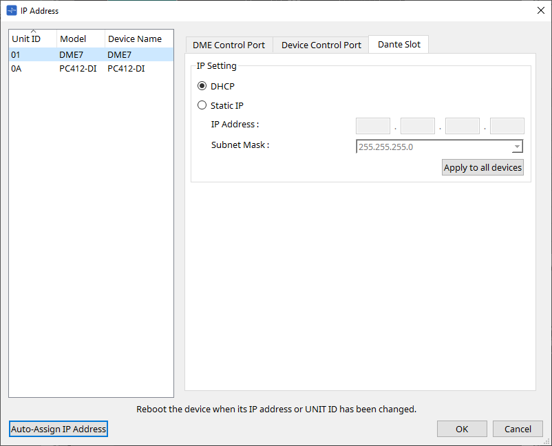
|
Use Dante Controller to set the IP address for the Dante Port.
When setting this IP address, if you select “Manually Set IP Address,” make sure that the Dante Slot is set to the same network. |
■ For the Rio3224-D2 / Rio1608-D2
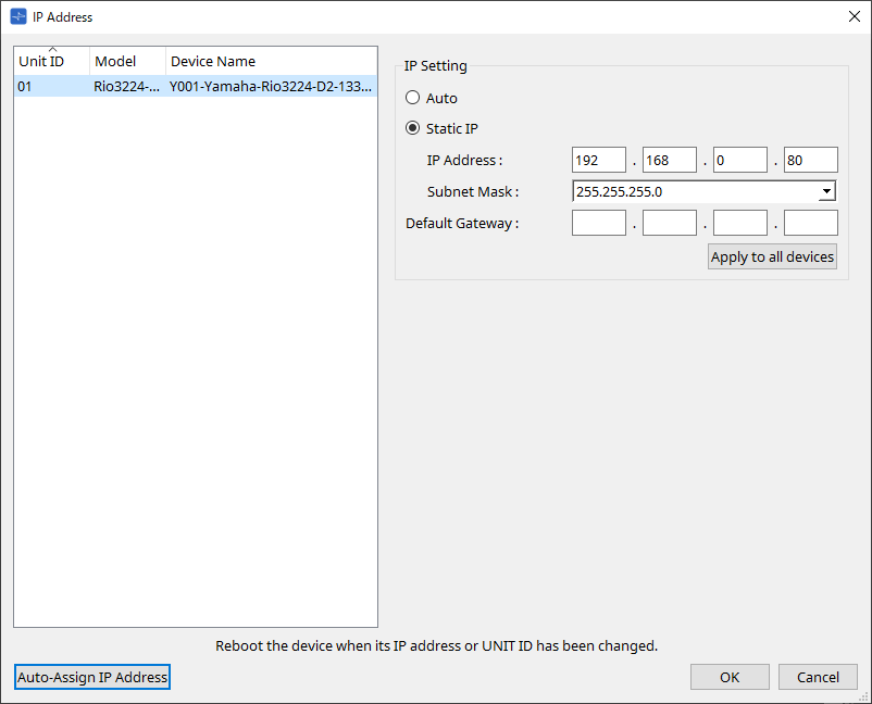
■ For the Rio3224-D3 / Rio1608-D3
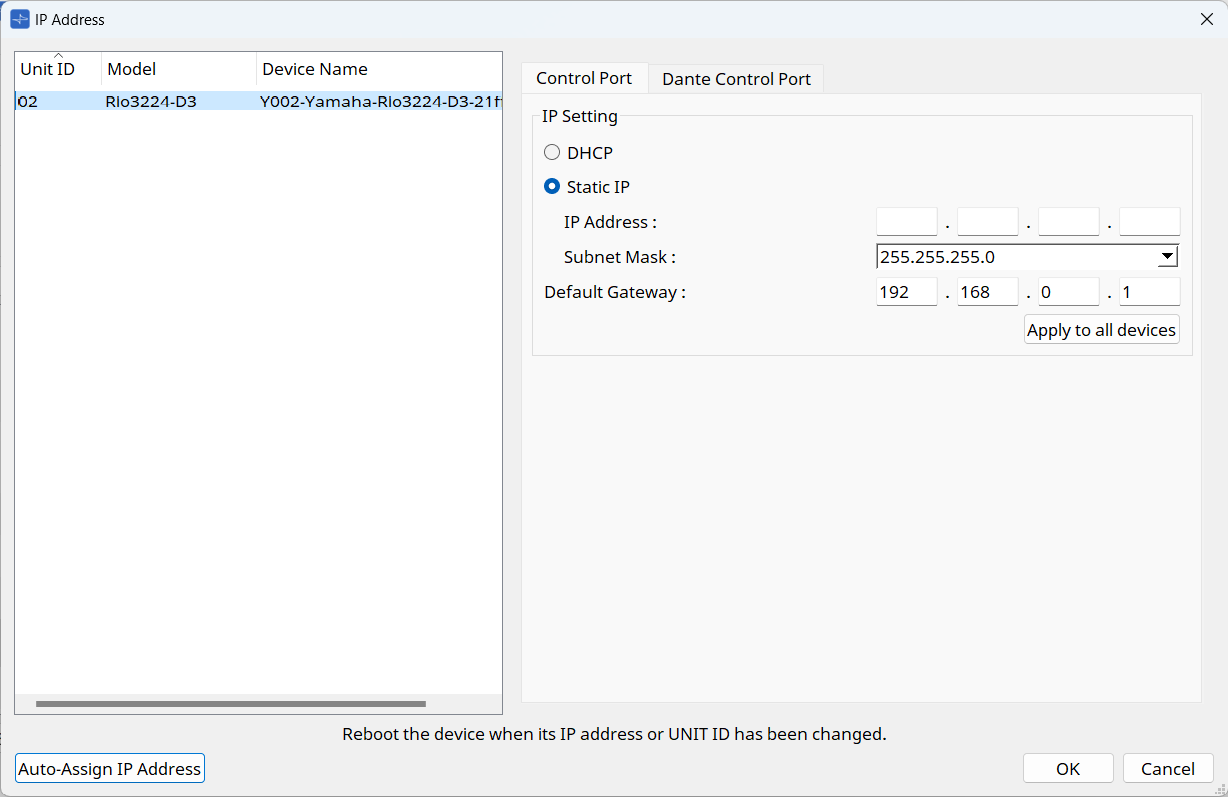
Control Port tab
Use this tab for the control via the Network terminal.
Dante Control Port tab
Use this tab for the control via the Dante Primary terminal.
At this time, the signals to control the main unit and the signals to control Dante are superimposed on the Dante port.
| To set the IP address used for controlling Dante via the Dante Primary/Secondary terminals, use Dante Controller. |
■ For the Tio1608-D / Tio1608-D2
■ For the RSio64-D
■ For the PC series
■ For the XMV series
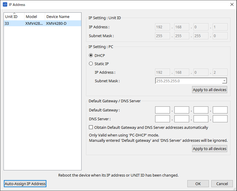
| If you don’t know the network address of the unit, we recommend that you use the DIP switch to set IP Setting to [UNIT ID]. |
■ For the MTX series/PGM1/EXi8/EXo8
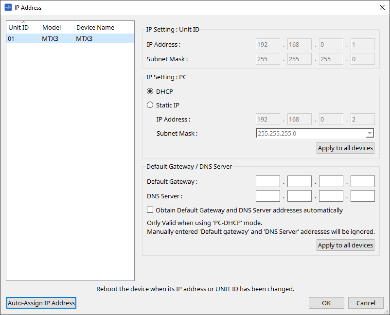
| If you don’t know the network address of the unit, we recommend that you use the DIP switch to set IP Setting to [UNIT ID]. |
■ For the RM-CG/RM-TT
■ For the DZR/DXS-XLF series
■ For the VXL1-16P
■ For the VXC2P
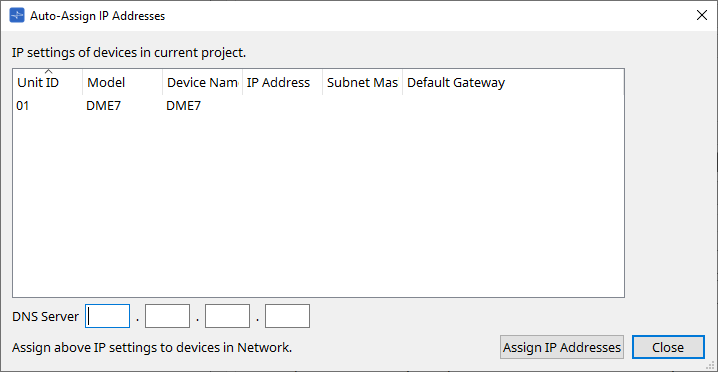
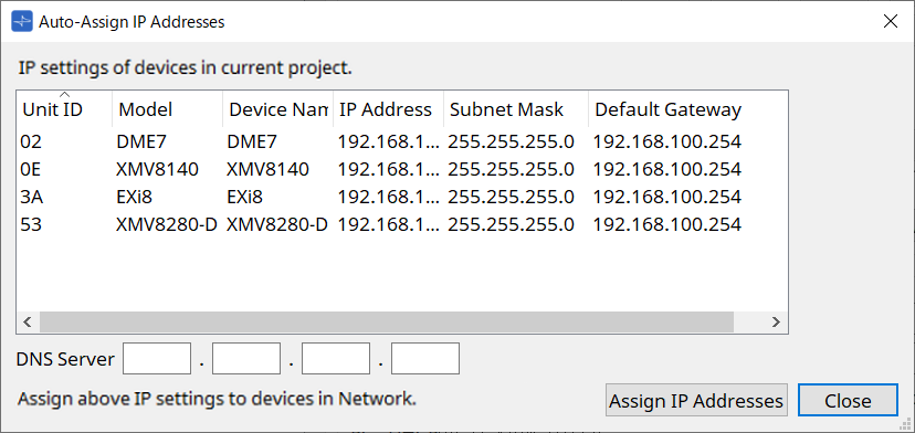
10.10. "Auto-Assign IP Addresses" dialog box
To open this dialog box, click the [Auto-Assign IP Addresses] button in the [IP Address] dialog box.
Information such as the IP address assigned to virtual devices specified in the "Match Devices by IP Address" dialog box is applied to the "IP Settings" dialog box in a single operation.
For details, refer to
"Settings for controlling devices across subnets"
.
-
Device list
Shows the devices for assignment and the IP settings to be assigned. -
DNS Server (PGM1 only)
This field is empty by default. Enter the DNS server address. -
[Assign IP Addresses] button
Applies the information shown in the device list to the "IP Address" dialog box. Even if the [DHCP] option button is selected in the "IP Address" dialog box, the [Static IP] option button is switched to the enabled state. -
[Close] button
Closes the dialog box.
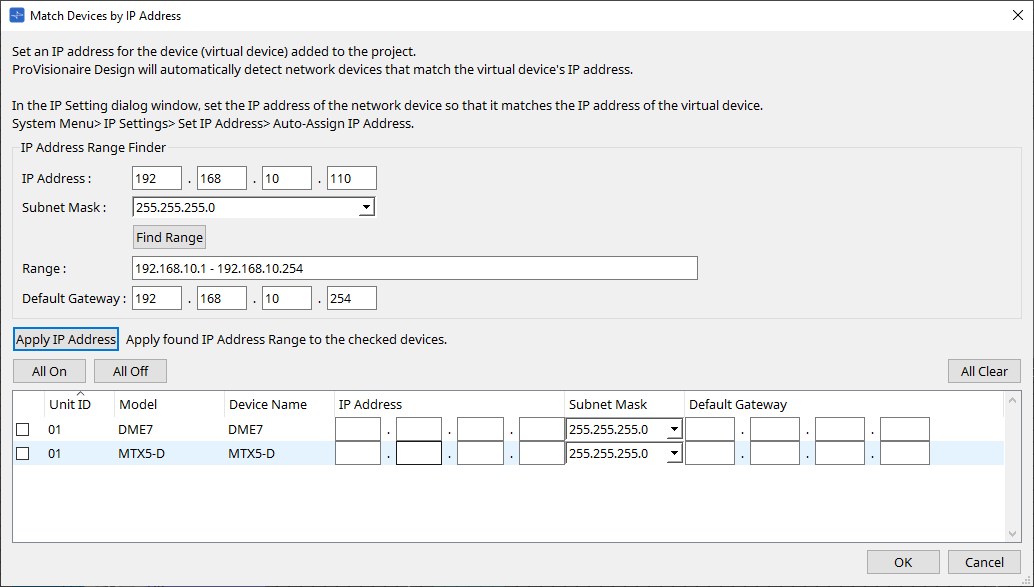
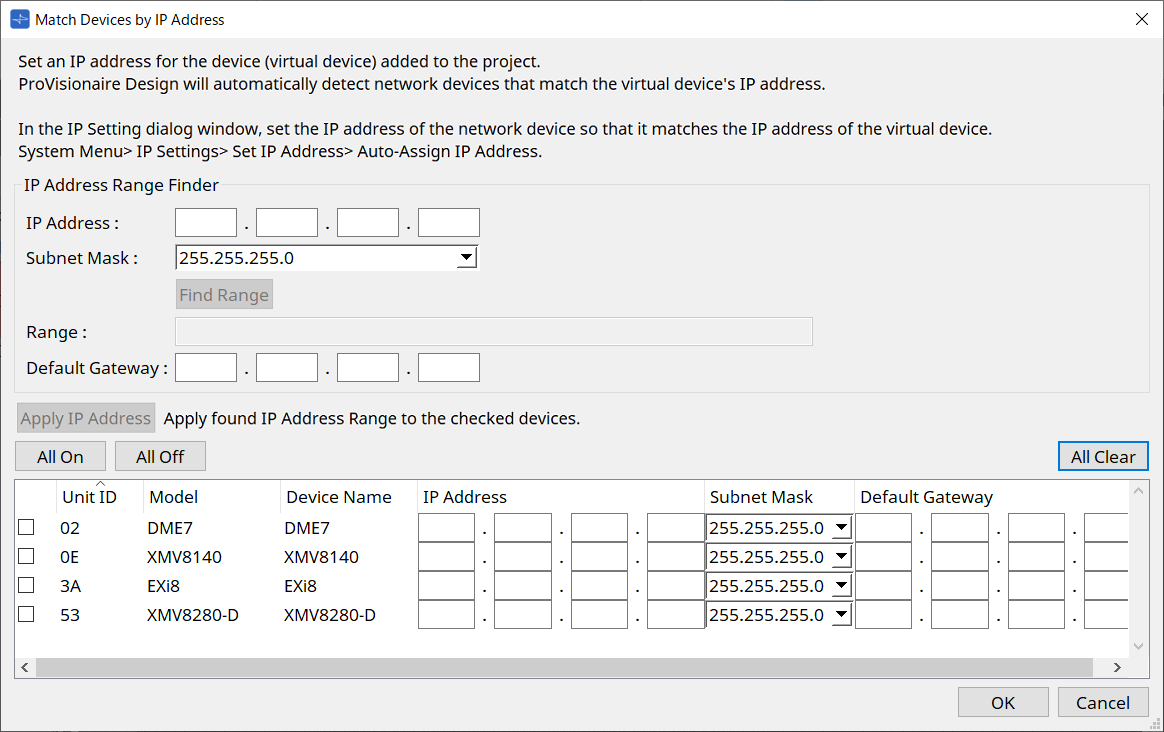
10.11. "Match Devices by IP Address" dialog box
When you assign an IP address to a virtual device in this dialog box, ProVisionaire Design searches for devices on the network by IP address.
If you want to control a system that is on a different subnet than ProVisionaire Design, make settings here.
For the procedure, refer to
"Settings for controlling devices across subnets"
.
Dante audio communication is not possible between devices that are on different subnets.
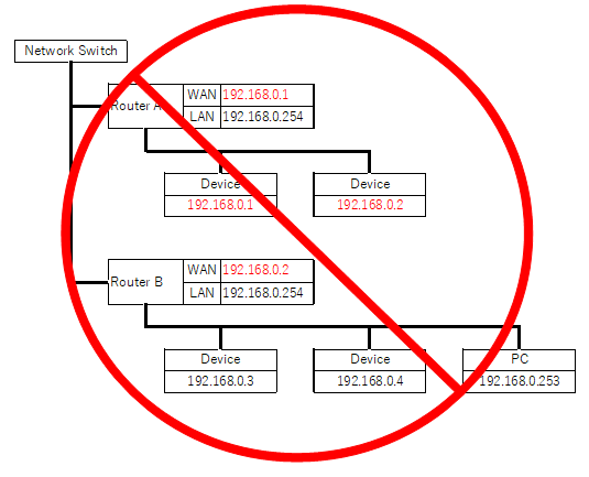
Set the IP addresses so that they are unique for the entire communication path. If devices of the same IP address exist on the communication path, they might not be distinguishable.
-
IP Address Range Finder
This section enables you to calculate the range of IP addresses that can be assigned.-
[IP Address]
Enter the IP address that you want to use. -
[Subnet Mask]
Select the subnet mask. -
[Find Range] button
When you click this, the range that can be specified is calculated from the IP address and subnet mask that you input. -
[Range]
Shows the calculated range of IP addresses. -
[Default Gateway]
Shows the calculated default gateway.
-
-
[Apply IP Address] button
When you click this, the IP address calculated in "IP Address Range Finder" and the default gateway are applied to the devices in the device list. -
[All On] button
Selects all devices in the device list to be affected by [Apply IP Address]. -
[All Off] button
Deselects all devices in the device list from being affected by [Apply IP Address]. -
[All Clear] button
Deletes the IP address information of the devices. -
Device list
Here you can view and edit the settings of the devices in the device list.-
Check box
If this is selected, [Apply IP Address] will apply to this device.
-
-
[IP Address]/[Subnet Mask]/[Default Gateway]
Here you can view and edit the device’s IP address, subnet mask, and default gateway.-
[OK] button
Applies the settings and closes the dialog box. -
[Cancel] button
Discards the settings and closes the dialog box.
-
10.11.1. Settings for controlling devices across subnets
If you are controlling devices on a subnet that is different than that of ProVisionaire Design, all devices are distinguished by their IP address.
For this reason, it is necessary to make settings so that the IP settings of devices placed in ProVisionaire Design (these are called virtual devices) match the IP settings of devices on the network (these are called real devices).
The IP settings of virtual devices are made in the
"Match Device by IP Address" dialog box
, and the IP settings of real devices are made in the
"IP Address" dialog box
.
Set the IP addresses so that they are unique for the entire communication path. If devices of the same IP address exist on the communication path, they might not be distinguishable.
First, use the "Match Device by IP Address" dialog box to specify IP addresses for the virtual devices.
-
Place a device in the "Project" sheet.
-
In ProVisionaire Design’s [System] menu, click [Match Device by IP Address].
The "Match Device by IP Address" dialog box opens.
-
In "IP Address Range Finder," use the [IP Address] text box to enter a representative IP address of the subnet to which the device to be searched is connected.
-
In "IP Address Range Finder," use the [Subnet Mask] list box to select the subnet mask.
-
In "IP Address Range Finder," click the [Find Range] button.
The vaild IP addresses’s range is shown in the "Range" field, and an IP address candidate for the default gateway is shown in the [Default Gateway] text box.
If the default gateway IP address is wrong, edit it. -
Check the checkbox of the virtual device for which you want to set the IP address.
-
Click the [Apply IP Address] button.
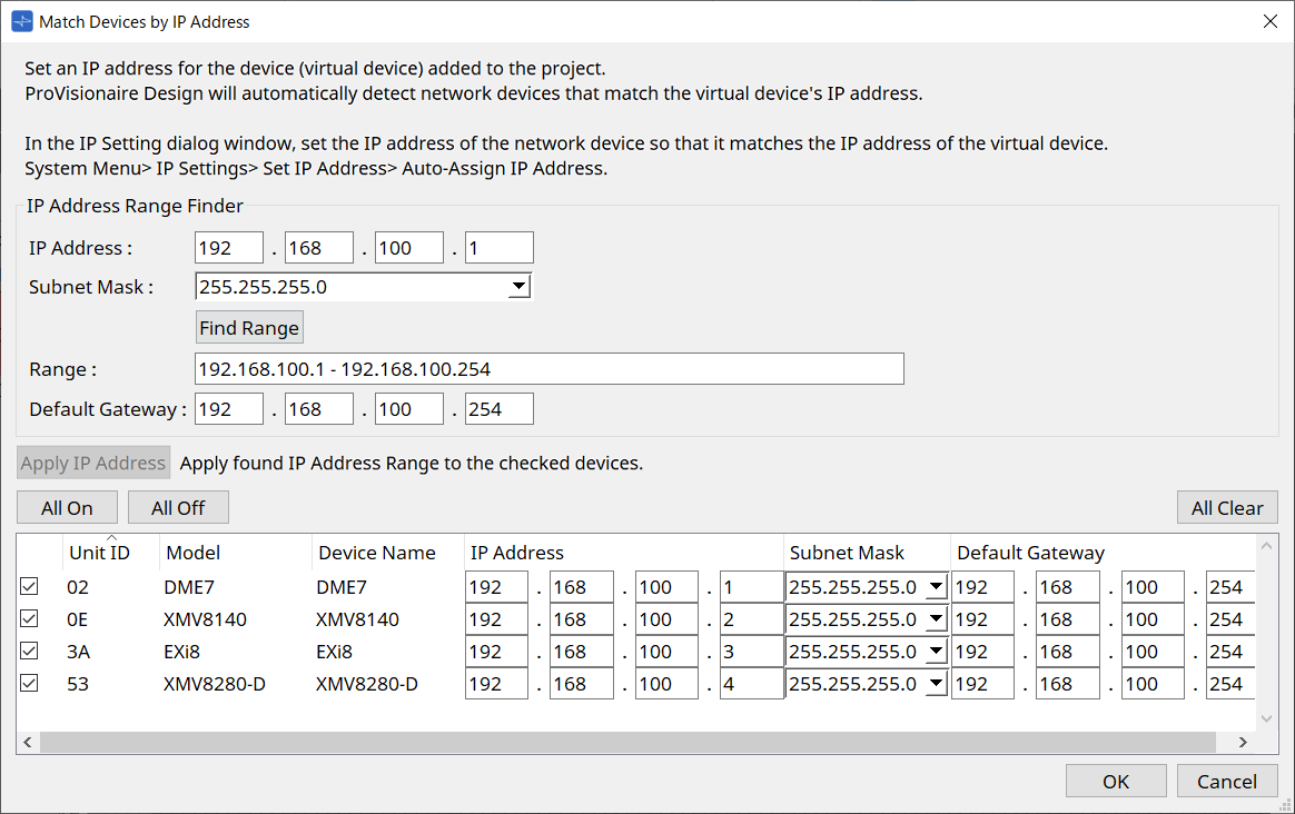
A static IP address is set for the virtual device.
-
Click the [OK] button.
To assign an IP address to a real device, you can either make settings by operating the real device, or you can use the "IP Address" dialog box to specify an IP address for the real device.
Here we will explain how to use the “IP Address” dialog.
Next, we will explaine the procedure for setting the IP address set for the virtual device to the real device.
-
Set the Unit ID of the real device to match the virtual device.
-
Connect the real device to the same subnet as ProVisionaire Design so that it can be discovered by ProVisionaire Design.
For details, refer to the owner’s manual of each device. -
While still offline, click [IP Settings] in the [System] menu of ProVisionaire Design.
If the "Network Setup" dialog box appears, sselect the same network as ProVisioniare Design.
-
When all real devices are shown in the "IP Settings" dialog box, click the [Set IP Address] button.
The "IP Address" dialog box opens.
-
Click the [Auto-Assign IP Addresses] button.
In the Match Device by dialog box, a list of IP addresses set for virtual devices is displayed.
Set the DNS Server as required.
-
Click the [Assign IP Addresses] button.
Reflect the settings of the virtual device to the real device whose Model and Unit ID match those of the virtual device.
-
Click the [OK] button.
The IP address, subnet mask, and default gateway settings are sent to the real devices.
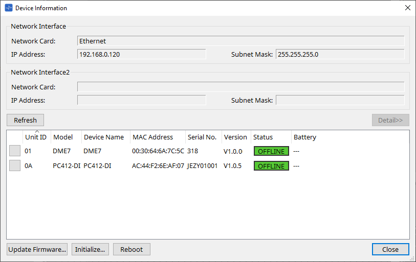
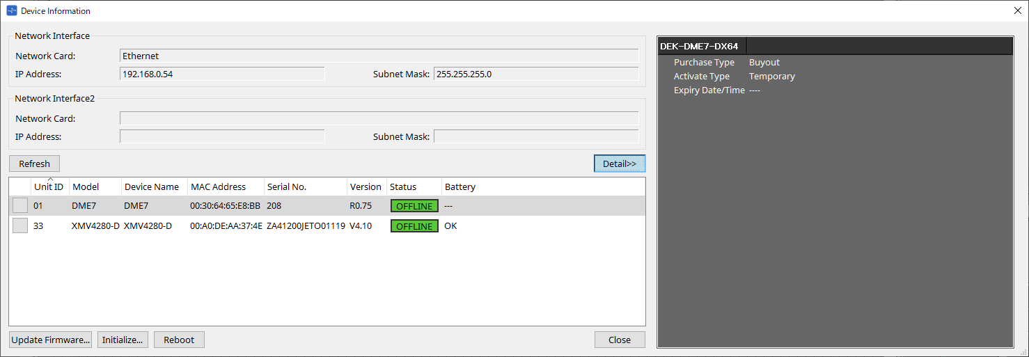
10.12. "Device Information" dialog box
To open this dialog box, click [Device Information] from the [System] menu on the menu bar.
This lists information for the devices on the network, allowing you to update their firmware or restart them.
-
Network Interface
Shows the name/IP address/subnet mask of the network card currently selected in the "Network Setup" dialog box. -
[Refresh] button
Searches again for devices on the network.
This cannot be clicked while an update is in progress. -
[Detail>>] button
Switch this button on to display to the right the information specific to the device that is currently selected on the device list. -
Device list
-
Identify button
When you press this button located at the left of the Unit ID, the indicators of the corresponding device will flash for several seconds. -
Unit ID / Model / Device Name
These columns indicate the device Unit ID, device model name, and device name. If there is a UNIT ID conflict, an
indication is shown.
To change the device name, use the [Device Name] field in the “Properties” area of the “Project” sheet.If different types of devices are used, the same Unit ID can be used for them.
However, if the MTX series unit is set to Unit ID mode, the IP address will be automatically set to 192.168.0..
In this case, you must set unique Unit IDs so that they will not overlap (conflict) among all devices. -
MAC Address
Shows the MAC address that is specified for the device. -
Serial No.
Shows the serial number of the device. -
Version
Shows the firmware version. -
Status
Shows the online or offline status.
When updating a device, the progress is shown. -
Battery (MTX series and XMV series units only)
Shows the remaining battery capacity of the device.
-
|
EMPTY |
The remaining amount is 0–0.5V. Immediately stop using the unit, and contact a Yamaha service center. |
|
LOW |
The remaining amount is 0.5–2.5V. Contact a Yamaha service center as soon as possible. |
|
OK |
The remaining amount is 2.5–3.5V. There is no problem. |
|
N/A |
There is no internal battery. |
-
[Update Firmware] button
Updates the firmware. Please note that you can do so only for the online devices.
Click this button to open the "Update Firmware" dialog box . -
[Initialize] button
Initializes the device.
Click this button to open the "Initialize" dialog box . -
[Reboot] button
Reboots the device. -
[Close] button
Closes the dialog box.
This cannot be clicked while an update is in progress.
10.12.1. “Detail>>” area
This area displays information specific to the target device.
■ For the DME
This area displays device information for each Device License that is activated for the device.
-
Title
Indicates the license name. -
Purchase Type
Indicates “Buyout” or “Trial.” -
Activate Type
This information appears only if the Purchase Type is “Buyout.”-
Temporary
With this type, you can activate and deactivate the license. -
Permanent
With this type, you cannot deactivate the license. -
Timed
With this type, the license features an expiration date. -
Activate Date/Time
Indicates the date and time at which you activated the license.
-
-
Expiry Date/Time
If the Purchase Type is “Trial” or the Activate Type is “Timed,” this field indicates the date and time at which the license expires.
Otherwise, it indicates “---.”
For license management, see the "Device License Activation Guide".
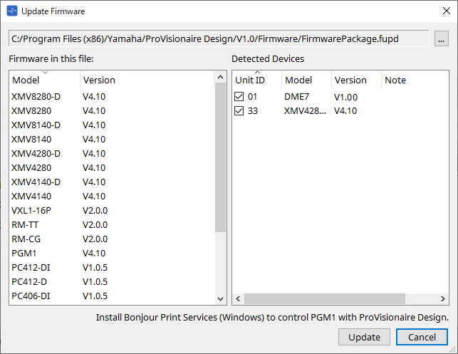
10.13. "Update Firmware" dialog box
To open this dialog box, click the [Update Firmware] button in the [Device Information] dialog box.
Update the firmware of a supported unit.
For details on how to update the Dante firmware, refer to the "Dante Firmware Update guide" .
| The DME10/DME7 updates the Dante firmware at the same time as updating the firmware of the unit. |
-
Files
Shows the currently selected update file (.fupd). -
[…] button
Click this button to select an update file. Clicking this button opens the "Select Folder" dialog box; select an .fupd file.
| When installing ProVisionaire Design, the .fupd file included in the compressed file is also copied to the Program Files (x86) folder. This file is automatically selected when the dialog is opened. |
-
Firmware in this file
Shows the contents of the update file. -
Detected Devices
Shows the detected devices.-
Check boxes
Enables you to select a target device to update. -
Unit ID
Indicates the UNIT ID of the device. -
Type
Indicates the model name of the device. -
Version
Shows the firmware version of the device.
-
| To control the PGM1 from ProVisionaire Design, you must first install Bonjour Print Services (Windows). |
-
[Update] button
Executes the update.
If a file is not selected, this button will be unavailable and cannot be clicked. -
[Cancel] button
Closes the dialog box without updating.
|
An alert appears if a device incompatible with ProVisionaire Design is detected.
Refer to the Yamaha Pro Audio website for information on compatibility between ProVisionaire Design and various devices. |
|
You must be logged in to update your RM series.
Please refer to the chapter of RM-CG/RM-TT. |
|
The DZR/DXS-XLF series cannot be updated using ProVisionaire Design.
Update them using the DZR-D/DXS XLF-D Firmware Updater or a USB memory. For more information, refer to the Yamaha Pro Audio website. |
|
Rio-D3 series cannot be updated using ProVisionaire Design.
Update them using the R Remote. For more information, refer to the Yamaha Pro Audio website. |
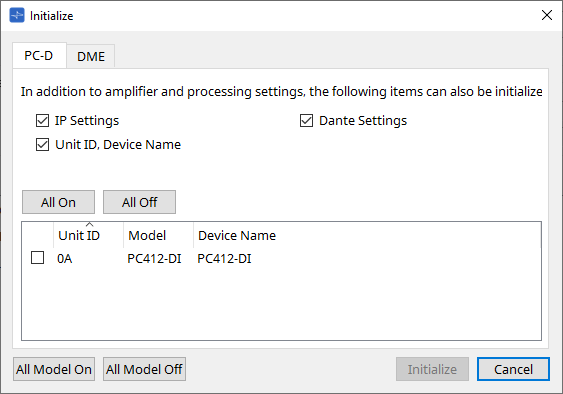
10.14. "Initialize" dialog box
To open this dialog box, click the [Initialize] button in the [Device Information] dialog box. This dialog box enables you to initialize the device settings.
The applicable products are the PC series, DME10, DME7, RM-CG, RM-TT, DZR series, and DXS-XLF series.
Select the tab for the product you wish to initialize.
■ For the PC series
-
Check boxes
Add a check mark to the check boxes for the items you wish to initialize.-
IP Settings
If this item is checked, the device IP settings will also be initialized. -
Unit ID, Device Name
If this item is checked, the device’s Unit ID and the name will also be initialized. -
Dante Settings
If this item is checked, the Dante-related settings for the device will also be initialized.
-
-
[All On] button
Adds a check mark to the check boxes for all devices. -
[All Off] button
Clears the check mark from the check boxes for all devices. -
Check box
Add a check mark to a device that you wish to initialize.-
Unit ID / Model / Device Name
These columns indicate the device Unit ID, device model name, and device name.
To change the device name, use the [Device Name] field in the “Properties” area of the “Project” sheet.
-
-
[All Model On] button
Adds a check mark to the check boxes for all devices on all tabs. -
[All Model Off] button
Clears the check mark from the check boxes for all devices on all tabs.
-
[Initialize] button
Executes initialization.
| The Unit ID and Device Name settings on the Dante device will not be initialized if its “Dante Device Lock” setting is turned on. |
-
[Cancel] button
Closes the dialog box without updating.
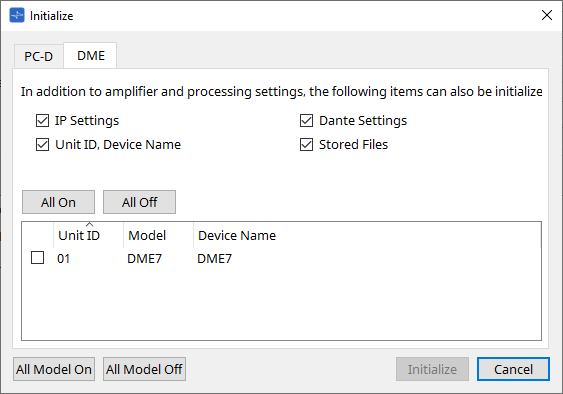
■ For the DME10/DME7
-
Check boxes
Add a check mark to the check boxes for the items you wish to initialize.-
IP Settings
If this item is checked, the device IP settings will also be initialized. -
Unit ID, Device Name
If this item is checked, the device’s Unit ID and the name will also be initialized. -
Dante Settings
If this item is checked, the Dante-related settings for the device will also be initialized. -
Stored Files
If this item is checked, the files saved on the unit using the File Storage function will also be initialized.
-
| Initializing the device does not affect any activated licenses. |
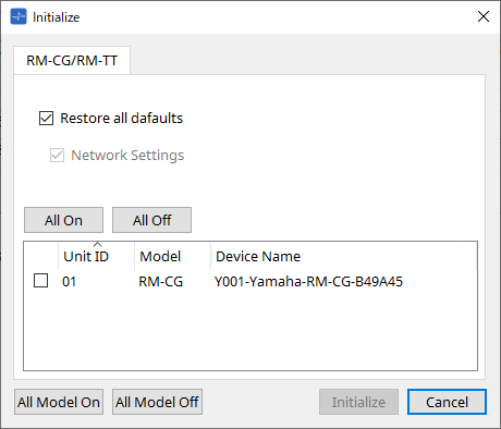
■ For the RM-CG, RM-TT
-
Check boxes
Add a check mark to the check boxes for the items you wish to initialize.-
Restore all defaults
If you add a check mark to this check box, all items will be initialized. The “Network Settings” items will also be initialized automatically. -
Network Settings
If this item is checked, the network settings for the device will also be initialized.
-
|
You must be logged in to initialize the RM series.
Please refer to the chapter of RM-CG/RM-TT. |
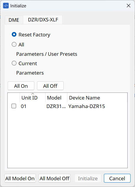
■ For the DZR series/DXS-XLF series
-
Radio buttons
Select from 3 types.-
Reset Factory
Resets to the factory settings. -
All
Initializes the parameters and user presets while keeping the network settings. -
Current
Initializes only the parameters while keeping the network settings and user presets.
-
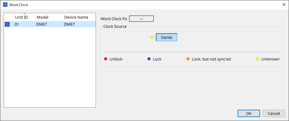
10.15. "Word Clock" dialog box
To open this dialog box, click [Word Clock] from the [System] menu on the menu bar. This dialog box enables you to modify the word clock settings for the device.
Target models include MTX series, XMV series (excluding Dante models), and DME10/DME7 that are added to the project.
-
Device list
This lists the devices whose word clock can be changed. Click the device whose detailed word clock settings you want to edit; the edit screen for that device will appear. The icon at the left of the UNIT ID indicates what is specified as the clock source.
| Icon | Clock source |
|---|---|
|
|
Dante |
|
|
Internal |
|
|
Mini-YGDAI card |
|
None |
YDIF |
-
Word Clock Fs
This indicates the word clock of the device. When online, this indicates the word clock value for the device. When the device is offline, this field indicates “---.” -
Clock Source
Use these buttons to select the word clock source. A indicator showing the status is displayed at the left of buttons that can be selected. When offline the status cannot be detected, so all indicators will be yellow.-
For the MTX3, XMV
You can select one of the internal clocks (44.1 kHz, 48 kHz), or YDIF. -
For the MRX7-D/MTX5-D
You can select Dante, YDIF or Mini-YGDAI Card. -
For the DME
You can select only Dante.
-
| Indicator | Status |
|---|---|
|
|
Unlocked. |
|
|
Locked. |
|
|
Locked but not synchronized. |
|
|
The clock status cannot be detected because an external device is not connected or because there is no valid clock input. |
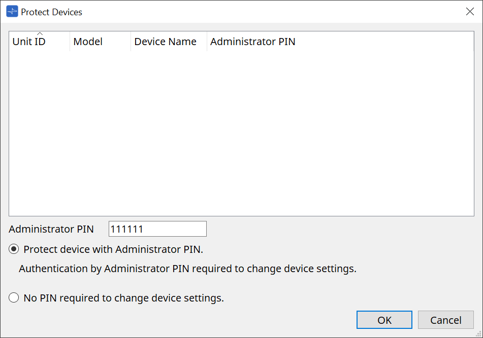
10.16. "Protect Devices" dialog box
To open this dialog box, click [Protect Devices] from the [System] menu on the menu bar.
You can specify an Administrator PIN for the device to prevent people other than the administrator from modifying the device settings. If you set an Administrator PIN, you will be required to enter the Administrator PIN when you try to make an online connection between the device and ProVisionaire Design or to specify various device settings. Please be aware that if you forget the Administrator PIN, you will be unable to modify device settings.
-
[Device] list
This area lists devices for which protection via the Administrator PIN has been canceled or for which an Administrator PIN has not yet been set.-
Unit ID / Model / Device Name
These columns indicate the device Unit ID, device model name, and device name.
To change the device name, use the [Device Name] field in the “Properties” area of the “Project” sheet. -
Administrator PIN
Indicate the Administrator pin in which devices that have unlocked the PIN.
-
-
[Administrator PIN] text box
In this field, enter the Administrator PIN for the device. (The code should be six alphanumeric characters drawn from numbers 0 through 9 and letters a, b, c, d, e, and f. The code is not case sensitive. A blank PIN cannot be specified.) -
[Protect device with Administrator PIN.] option button
If you try to change the device settings, you will be required to enter the PIN. -
[No PIN required to change device settings.] option button
Cancels device protection via the Administrator PIN. -
[OK] button
Sends the protection settings to the device. -
[Cancel] button
Discards the settings and closes the dialog box.
10.17. "Clock" dialog box
To open this dialog box, click [Clock] from the [System] menu on the menu bar.
The internal clocks for all connected devices are automatically updated to match the date and time on the computer each time the devices come online.
If you transmit the computer’s date and time information from this dialog box, the date and time will be updated on any unit that is connected to the same network, regardless of its online/offline status.
10.17.1. RM Series
This section applies to the settings for the RM series units.
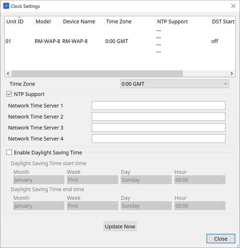
-
Device list
Displays the current device settings. -
[Time Zone]
Specifies the time zone. -
[NTP Support] check box
If this check box is selected, the NTP server is used. -
[Enable Daylight Saving Time] check box
If this check box is selected, the daylight saving time indication will be enabled.
10.17.2. Non-RM Series
This section applies to the settings for units that are not part of the RM series.
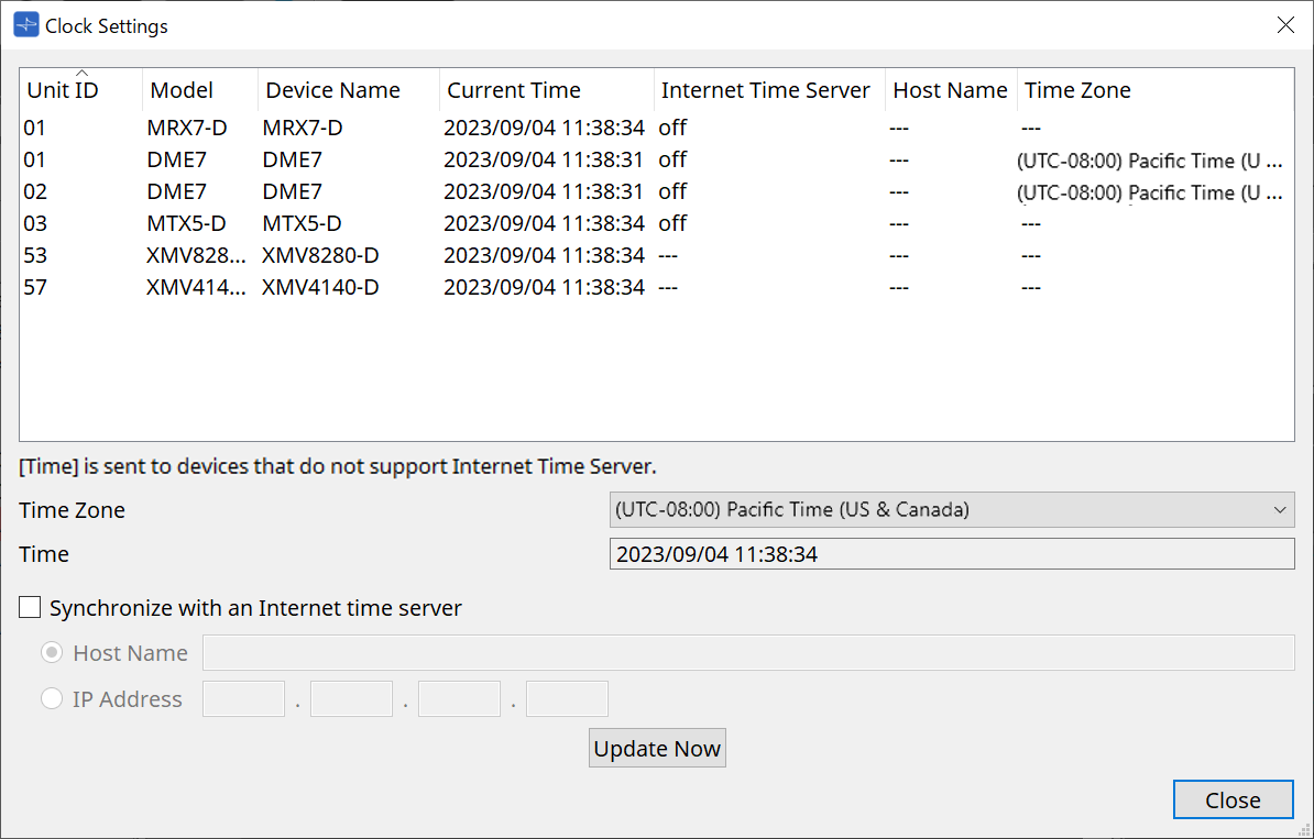
-
Device List
Displays the current device settings.The settings are sent when ProVisionaire Design and the device are brought online.
-
[Time zone]
Sets the time zone. The computer’s time zone is set by default. -
[Time]
Displays the date and time according to the time zone. -
[Synchronize with an Internet time server] checkbox
Acquires the time information from the specified time server and updates the device’s internal clock.
[Time] is sent to devices that do not support a time server.-
[Host name]
Sets the host name of the time server. -
[IP Address]
Sets the IP address of the time server.
-
![]() Notice
Notice
-
If you plan to specify an external time server, configure an Internet connection, and in the IP Address dialog box, specify the [DNS server address] and [Default gateway] as appropriate for the connection environment.
If you specify an external time server, make sure that the server is reliable. If you specify an unreliable server, you may be exposed to certains risks, such as an infection by a computer virus. -
When using ProVisionaire Edge, we recommend disabling the "Synchronize with an Internet time server" option. If it is enabled, the correct time may not be displayed.
-
[Update Now] Button
Click to update the device settings at the same time. -
[Close] button
Closes the dialog box.
10.18. "Daylight Saving Time" dialog box
To open this dialog box, click [Daylight Saving Time] from the [System] menu on the menu bar.
This specifies the daylight saving time setting of the devices connected to the same network, regardless of their online/offline state.
The target device is the DME10/DME7/MTX series.
| For RM series units, use the “Clock” dialog box to make the settings. |
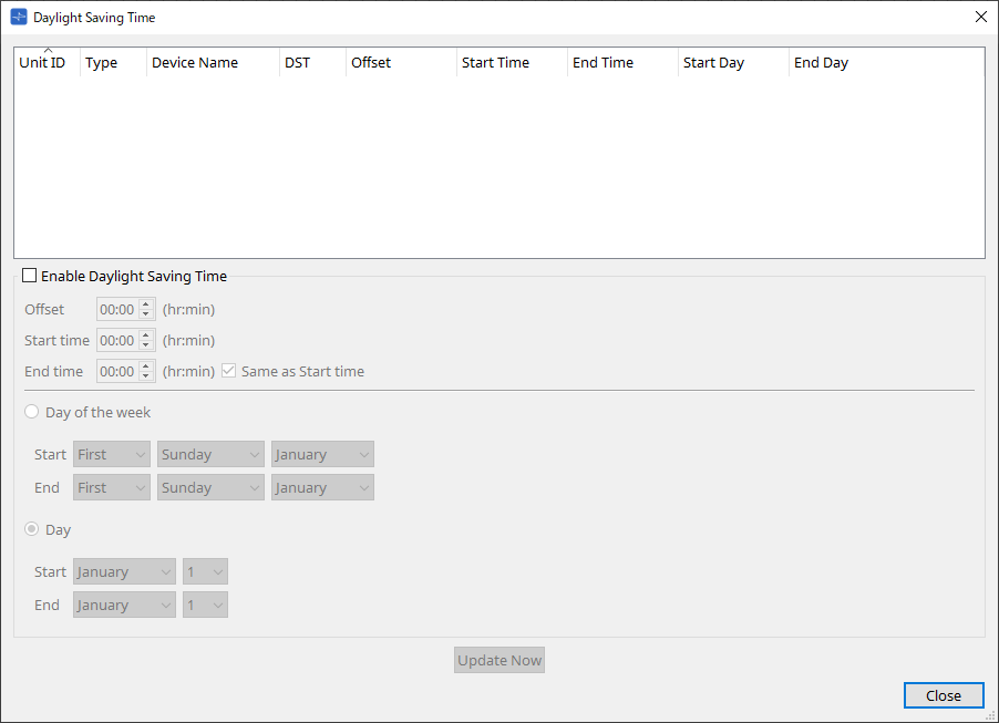
-
Device List
Displays the current device status. -
[Enable Daylight Saving Time] check box
Daylight saving time will be enabled if this check box is selected.If the “Automatically adjust daylight saving time” check box is selected in the computer’s “Date and Time” settings, you must also select the [Enable Daylight Saving Time] check box in the “Daylight Saving Time” dialog box. -
Offset
Specifies the amount of time by which daylight saving time is earlier than standard time. -
Start time
Specifies the time when daylight saving time begins.
For example if you set Offset as 01:00 and Start time as 12:00, the clock will be set to 13:00 when the time reaches 12:00 of the day on which daylight saving time begins.
-
-
End time
Specifies the time when daylight saving time ends. If this is the same as the start time, select [Same as Start time].
For example if you set Offset as 01:00 and End time as 12:00, the clock will be set to 11:00 when daylight saving time reaches 12:00 on the last day of daylight saving time. If the [Same as Start time] check box is selected, daylight saving time will automatically be cancelled and revert to standard time on the last day of daylight saving time at the time specified by the Start time.-
Day of the week
If this is on, the term of daylight saving time will be specified as a day of the week. Use Start and End to specify which day of which week will be the start and end of daylight saving time. For example to specify the first Sunday in April, choose “First,” “Sunday,” and “April”; to specify the last Sunday in October, choose “Last,” “Sunday,” and “October.” -
Day
If this is on, the term of daylight saving time will be specified as a day of a month. Use Start and End to specify the dates that will be the start and end of daylight saving time. -
[Update Now] button
When you click this, the device’s internal clock is updated according to the settings. -
[Close] button
Closes the dialog box.
-
| Events that are assigned within two hours before or after the beginning or end of daylight saving time in the “Scheduler” dialog box will not be executed correctly. |
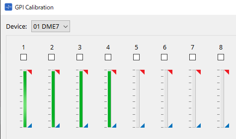
10.19. "GPI Calibration" dialog box
To open this dialog box, click [GPI Calibration] from the [System] menu on the menu bar.
Here you can calibrate the input voltage detection range for the [GPI] connector of the device. Available only when online. These settings adjust the detection range in order to stabilize the input voltage of the [GPI] connector.
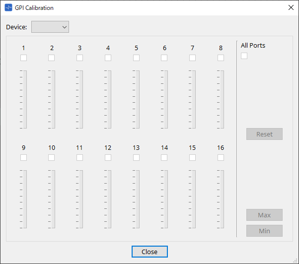
-
[Device:]
Enables you to select a target device to calibrate. -
[All Ports] check box
Selects the check boxes of all channels. -
[Ch] check boxes
Calibration will be applied to the channels whose boxes are selected -
Calibration data
The input voltage is shown in real time as a graph.
-
[Reset] button
Calibration will be reset for the channels whose boxes are selected. -
[Max] button
Sets the current input voltage of the selected channels to the maximum value.
The maximum value you set is shown by .
.
-
[Min] button
Sets the current input voltage of the selected channels to the minimum value.
The minimum value you set is shown by .
.
Calibration procedure
-
Connect your external device to the DME/MTX’s [GPI] connector.
-
Select the check box of the channel numbers for which you want to perform calibration.
If you want to select all channels, select the [All Ports] check box. -
To specify the detection range, increase the input from the external device to the maximum and click the [Max] button; then decrease the input to the minimum and click the [Min] button.
This lets you specify the optimal detection range as appropriate for voltage drop caused by wiring or due to the specifications of your devices.
|
• The threshold for on/off switching will be the center value between the maximum and minimum input voltage values (the sum of the maximum value and minimum value, divided by 2). To prevent malfunctions, you should allow plenty of range for detection.
• If the voltage has dropped because of cable length or noise, adjust the maximum and minimum input voltage values. Since voltage may become unstable, configure and set up your external circuit to ensure that there is ample distance between the maximum and minimum values. |
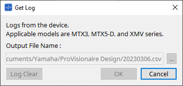
10.20. "Get Log from Devices" dialog box
To open this dialog box, click [Get Log from Devices] from the [System] menu on the menu bar.
A record of the MTX series/XMV system’s operation is stored as a “log” in the MTX series/XMV’s internal memory. In this dialog box you can output the logs of all MTX series/XMV units existing on the subnet to which your computer is connected, and save them as a file. The log file is in “.csv” format.
-
[Output File Name:] text box
Shows the location (absolute path) in which the log file is saved. You can also enter this directly. -
[…] button
Opens the file browser and selects the file that will be output as the log. -
[Log Clear] button
Deletes the log for all devices existing on the subnet. -
[OK] button
Outputs the log file and closes the dialog box. -
[Cancel] button
Cancels log file output and closes the dialog box.
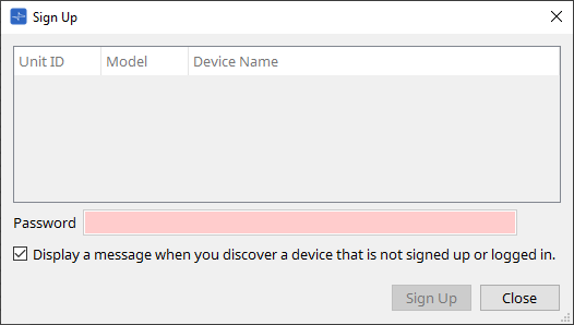
10.21. "RM Series Settings" > "Sign up" dialog box
To open this dialog box, click [RM Series Settings] from the [System] menu on the menu bar, and then click [Sign up…].
This dialog box enables you to set the initial password for an RM series unit.
To control the device from ProVisionaire Design, you must set an initial password.
-
Device List
Displays RM series units on the network for which an initial password has not been set.-
Unit ID / Model / Device Name
These columns indicate the device Unit ID, device model name, and device name.
To change the device name, use the [Device Name] field in the “Properties” area of the “Project” sheet.
-
-
[Password] text box
Enter a password here (4-16 alphanumeric characters). -
[Display a message when you discover a device that is not signed up or logged in.] check box
If this item is checked, and if ProVisionaire Design detects any devices for which the initial password has not been set or any devices that have not signed in, the “Sign Up” or “Login” dialog box will automatically appear.
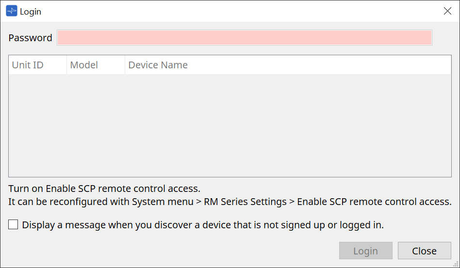
10.22. "RM Series Settings" > "Login" dialog box
To open this dialog box, click [RM Series Settings] from the [System] menu on the menu bar, and then click [Login…].
You must log in to be able to control the devices via ProVisionaire Design.
-
[Password] text box
Enter a password here (4-16 alphanumeric characters). -
Device List
-
Unit ID / Model / Device Name
These columns indicate the device Unit ID, device model name, and device name.
To change the device name, use the [Device Name] field in the “Properties” area of the “Project” sheet.
-
-
[Display a message when you discover a device that is not signed up or logged in.] check box
If this item is checked, and if ProVisionaire Design detects any devices for which the initial password has not been set or any devices that have not signed in, the “Sign Up” or “Login” dialog box will automatically appear. -
[Login] button
Executes log-in and closes the dialog box. -
[Close] button
Cancels log-in and closes the dialog box.
|
If the “Enable SCP remote control access” setting for a device has been turned off, it will automatically be turned on at the time of log-in.
To disable this setting, access the [System] menu > RM Series Settings > Enable SCP remote control access. |
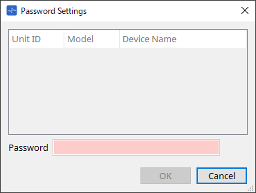
10.23. "RM Series Settings" > "Password Settings" dialog box
To open this dialog box, click [RM Series Settings] from the [System] menu on the menu bar, and then click [Password Settings].
This dialog box enables you to change the password for the devices.
-
Device List
Displays the logged-in device in the list.-
Unit ID / Model / Device Name
These columns indicate the device Unit ID, device model name, and device name.
To change the device name, use the [Device Name] field in the “Properties” area of the “Project” sheet.
-
-
[Password] text box
Enter a password here (4-16 alphanumeric characters).
Overwrites the existing password for all the devices with the new password. -
[OK] button
Sets the password and closes the dialog box. -
[Cancel] button
Discards the modified password and closes the dialog box.
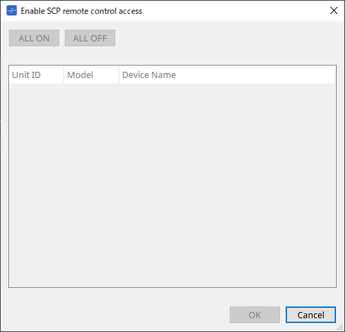
10.24. "RM Series Settings" > "Enable SCP remote control access" dialog box
To open this dialog box, click [RM Series Settings] from the [System] menu on the menu bar, and then click [Enable SCP remote control access].
To be able to modify the settings via a controller (such as ProVisionaire Design), you must turn on the “Enable SCP remote control access” setting.
-
Device List
-
Unit ID / Model / Device Name
These columns indicate the device Unit ID, device model name, and device name.
To change the device name, use the [Device Name] field in the “Properties” area of the “Project” sheet.
-
-
[ALL ON] button
Selects all devices. -
[ALL OFF] button
De-selects all devices. -
Check box
If you add a check mark to this check box and click the [OK] button, the “Enable SCP remote control access” setting will be enabled. -
[OK] button
Enables the setting and closes the dialog box. -
[Cancel] button
Discards the setting and closes the dialog box.
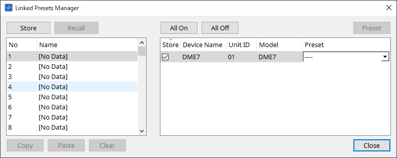
10.25. "Linked Presets Manager" dialog box
To open this window, click
 on the toolbar.
You can store or recall presets and snapshots for each device collectively.
A group of any presets for each device is called a “linked preset.”
This dialog box enables you to assign presets on the devices to a linked preset.
| The DZR series/DXS-XLF series cannot be stored nor recalled when in the offline state. |
Basic use is as follows.
-
In the list at left, select the store-destination link preset.
-
In the list at right, add a check mark to the devices that you want to store.
-
Click the [Store] button.
The preset is stored in the number you selected in step 1 for each device that you selected in step 2.
To remove a device from being a target of linked presets, select [----] in the [Preset] column of the list at right.
Note that the DME series and MRX7-D are not stored here.
After storing a linked preset, specify a stored snapshot for the DME series, or a stored preset for the MRX7-D in the "Preset" column.
If you specified presets on each device in advance, use the following procedure.
-
In the list at left, select the store-destination link preset.
-
In the list at right, clear the check box of the device on which a preset has been specified.
-
In the list at right, select the [Preset] of the device on which it was already stored.
-
Click the [Store] button.
-
[Store] button
Store the linked preset. When you store to an empty linked preset, the "Store Linked Preset" dialog box appears. -
[Recall] button
Recalls the selected linked preset. -
Link preset field
Selects the linked preset to store or recall. -
[Copy] button
Copies the selected linked preset. -
[Paste] button
Pastes the copied linked preset to the selected linked preset. -
[Clear] button
Erases the selected linked preset. -
[All On] button
Adds a check mark to the [Store] check box of all devices in the list. -
[All Off] button
Clears the check mark from the [Store] check box of all devices in the list. -
[Preset] button
Shows the device sheet of the currently-selected device. -
Device list
Shows a list of the devices with preset functionality that are registered in the project.-
[Store] check box
If this check box is selected, the preset selected in the [Preset] list box is overwrite-saved to devices whose [Store] check box is selected in the device list.
If the [Preset] list box is [----], it is overwrite-saved to the preset of the same number as the linked preset.
If settings are already stored in the preset number of the device, and that preset number is selected in the [Preset] list box, clear the check mark. -
Device Name / Unit ID / Model
These columns indicate the device name, device Unit ID, and device model name.
To change the device name, use the [Device Name] field in the “Properties” area of the “Project” sheet. -
[Preset] list box
Select the device’s preset that you want to link to the linked preset.
You can change the preset number after storing. If you want to exclude it from linked preset recall, select [----].
-
-
[Close] button
Closes the dialog box.
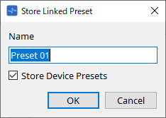
10.26. "Store Linked Preset" dialog box
In the "Linked Presets Manager" window, click the [Store] button to access this dialog.
-
[Name] text box
Enter a name for the linked preset. By default, this will be "Preset + preset number." You can’t store if the linked preset name field is empty. -
[Store Device Presets] check box
If this check box is cleared, the check box in the list at the right of the "Linked Presets Manager" window is cleared, and the device’s preset will not be overwrite-stored.
If you previously stored settings in the device’s preset number, clear this check box to prevent overwriting. The settings are stored with the [Store] check box cleared. -
[OK] button
Specifies the linked preset and closes the dialog box. -
[Cancel] button
Closes the dialog box without specifying the linked preset.
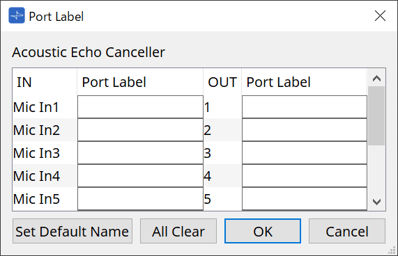
10.27. Port Label Dialog
With the port selected, click on the "Label" Value in the Properties area to display it.
All port names of the components, including the selected port, can be edited at once.
-
Component name
The component name containing the selected port is displayed at the top of the list. -
[IN]/[OUT] Field
Displays the default name of the port. -
[Port Label] Field
Displays/edits the port name. Press < Enter > to confirm the input and move the focus to the next port. The focus can also be moved using the cursor keys. -
[Set Default Name] Button
Sets the default name (the name displayed in the [IN]/[OUT] field) in the [Port Label] field. -
[All Clear] Button
Clears all port names. -
[OK] Button
Saves the settings and closes the dialog. -
[Cancel] Button
Closes the dialog without changing the settings.