DCP
27. DCP
27.1. Overview
The DME7/MRX7-D/MTX5-D/MTX3 parameters can be assigned to the operators of a digital control panel (DCP) such as the DCP1V4S, and controlled from the DCP. In addition, the brightness of the LEDs on the DCP unit can be set, as well as a panel lock. Settings cannot be made while in an online state (settings can only checked).
27.2. How to select the DCP to be connected
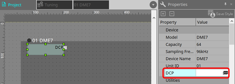
First, select DME7/MRX7-D/MTX5-D/MTX3 in the Project sheet, and select the DCP for the Properties area.
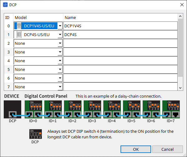
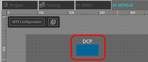
After that, use the screen below to select the DCP that has been connected to the DCP port.
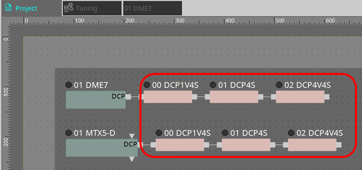
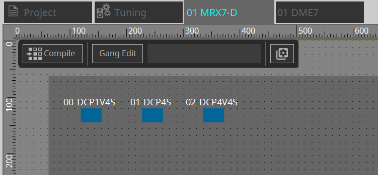
When DCP is selected, a module for DCP settings for each device on the "Project" sheet is added.
Click on the DCP setting module to specify the settings.
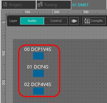
The DCP component is automatically added to the device sheet. Double-clicking a component opens the component editor.
■ For the DME7/MRX7-D
■ For the MTX series
27.3. Setting method for DME7
A DCP component can be added to a Parameter Set just like any other audio component and store/recall its current value in a snapshot.
■
How to register to Parameter Set
Parameters can be registered in a parameter set in the following ways.
| Registration source | Registration method |
|---|---|
|
Device sheet |
While holding down < Ctrl >, drag and drop the DCP component to the Parameter Set in the "Parameter Sets" area. |
|
Select "Add to Parameter Set" in the context menu. |
27.3.1. DCP component setting
Click on the DCP component in the Audio layer and specify the various settings.
-
[Clear All] button
Deletes the contents that have been set.
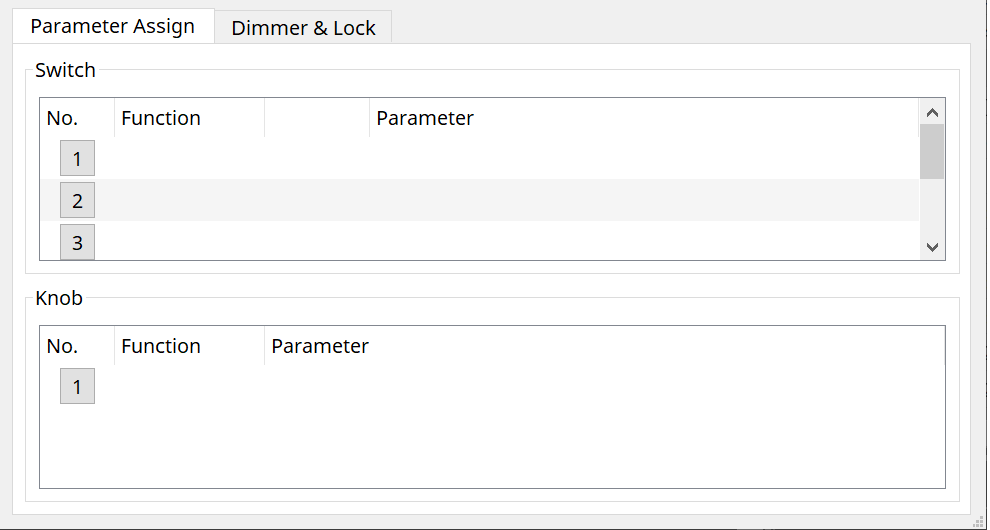
27.3.2. [Parameter Assign] tab
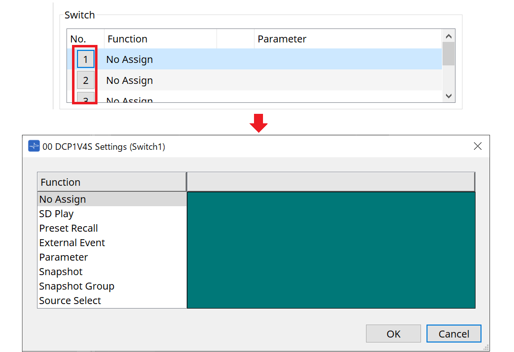
The setting dialog that is used to specify the settings for each operator is displayed when the No. icon for the operator (switch or knob) that you want to set is clicked. Assign DME7 parameters to each operator in the dialog.
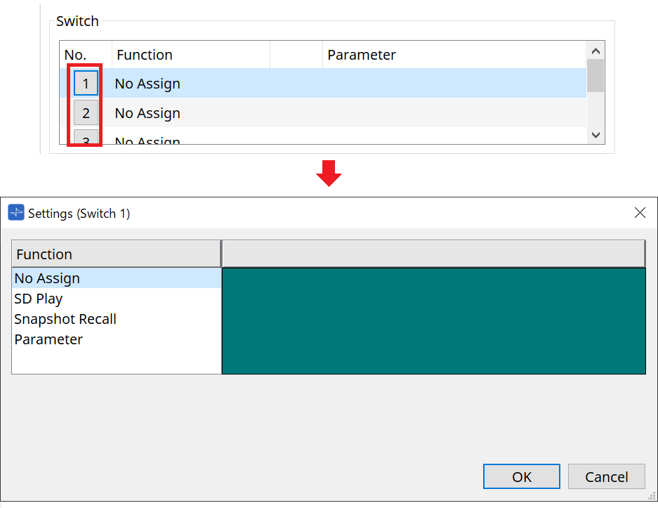
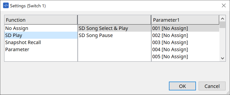
27.3.2.1. DCP component: Settings dialog (switch)
Click the No. icon of the DCP component editor to open it.
-
[OK] button
Saves the settings and closes the dialog box. -
[Cancel] button
Closes the dialog box without saving the changes.
Function
-
[No Assign]
Function is not assigned. -
[SD Play]
-
SD Song Select & Play
Plays the file specified in the [Parameter1] list.
For SD Card file settings, refer to "SD Card File Manager" dialog . -
SD Song Pause
Stops playing the file.
-
-
[Snapshot Recall]
Recalls the snapshot.
Snapshot can be registered in the following ways.
| Registration source | Registration method |
|---|---|
|
"Parameter Sets" area |
Drag and drop the snapshot into the green area of the "Settings" dialog box. |
-
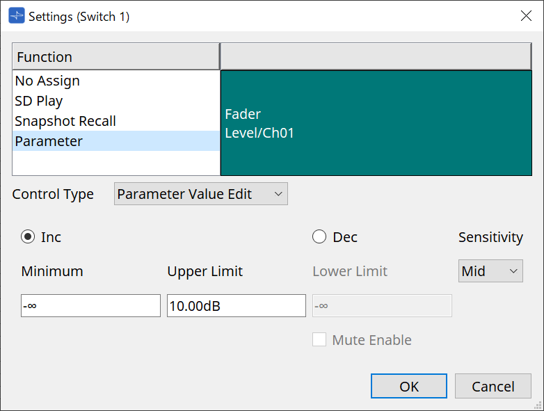
[Parameter]
Operate parameters with switches.
Parameters can be registered in the following ways.
| Registration source | Registration method |
|---|---|
|
Component editor |
While pressing and holding down < Ctrl >, drag and drop a parameter to the green area of the "Settings" dialog box. |
|
"Parameters" area |
Drag and drop a parameter to the green area of the "Settings" dialog box. |
Below is an example of assigning a parameter that changes continuously.
-
[Control Type] list box
If Parameter Value Edit is selected-
[Inc]
The parameter is added each time the switch is pressed.
You can set the movable range with Minimum/Upper Limit.
Click Minimum/Upper Limit to display controls. -
[Dec]
Subtracts the parameter each time the switch is pressed.
You can set the lower limit with Lower Limit.
Click Lower Limit to display the controls.-
[Mute Enable] check box
If this option is selected, the Mute state (–∞ dB) will be enabled if the level is lowered below the value specified by [Lower Limit].
-
-
[Sensitivity] list box
Sets the sensitivity of parameter changes in response to the downward operation of the DCP switch.
-
-
[Control Type] list box
If Direct Parameter Value is selected
When the switch is pressed, the parameter becomes the value specified by Value. -
[Control Type] list box
If Knob Assign is selected
When the switch is pressed, you can use the knob to operate the parameter assigned to the switch.
This function is only for DCP1V4S.
For the setting, refer to the knob section.
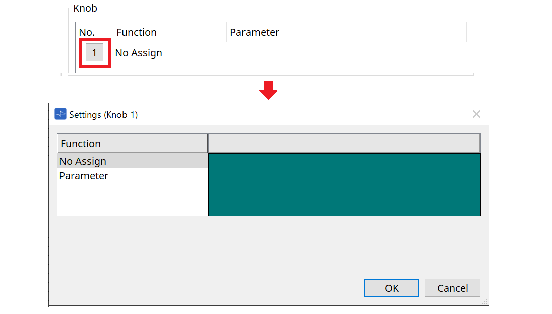
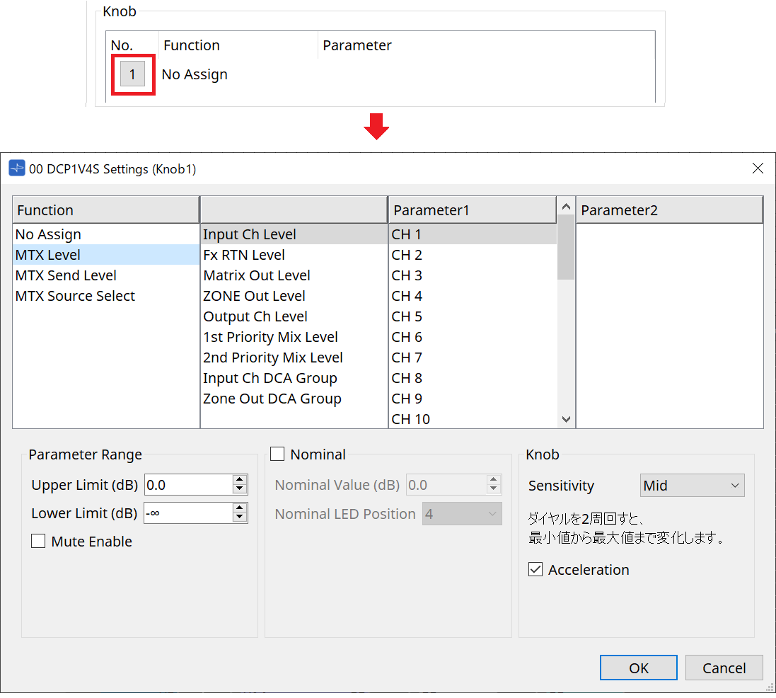
27.3.2.2. DCP component: Settings dialog (knob)
-
[Parameter]
Operate the parameters with the knobs.
Parameters can be registered in the following ways.
| Registration source | Registration method |
|---|---|
|
Component Editor |
While pressing and holding down < Ctrl >, drag and drop a parameter to the green area of the "Settings" dialog box. |
|
"Parameters" area |
Drag and drop a parameter to the green area of the "Settings" dialog box. |

-
[Parameter Range]
You can set the movable range with Lower Limit and Upper Limit.
Click Lower Limit/Upper Limit to display the controls.-
[Mute Enable] check box
If this option is selected, the Mute state (–∞ dB) will be enabled if the level is lowered below the value specified by [Lower Limit].
-
-
[Nominal]
By specifying the nominal value, you can assign a specific LED position as the normal volume setting. For example by specifying the center LED as the volume setting for normal use and setting the maximum value to the maximum volume that is allowable for the system, you can prevent damage to the system that might occur if the volume of the background music were raised during a noisy time.
If the check box is selected, the Nominal function will be on.
[Nominal Value] specifies the nominal value.
[Nominal LED Position] specifies the LED position that will light when the level reaches the nominal value. -
[Sensitivity]
Sets the sensitivity of parameter changes in response to the rotary operation of the DCP knob.
If [Acceleration] is on, the parameter will change faster if the knob is rotated more rapidly. If [Fast] is selected as the [Sensitivity], the [Acceleration] setting is dimmed and unavailable.
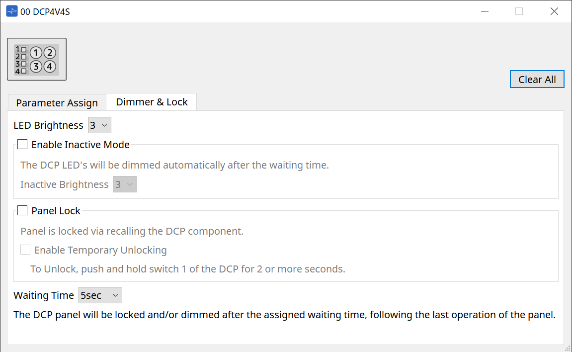
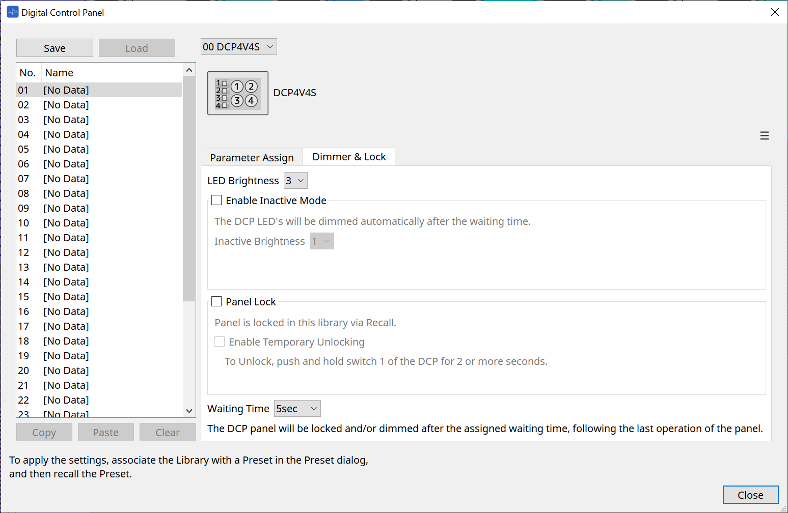
27.3.3. [Dimmer & Lock] tab
Sets the brightness of the MCP1’s display and switches, and the operation of the panel lock.
-
[LED Brightness] list box
Specifies the brightness of the DCP unit’s LEDs. Higher values will make the LEDs brighter.-
[Enable Inactive Mode] check box
If the check box is selected, the unit automatically enters inactive mode after a time duration specified in [Waiting Time].
[Inactive LED Brightness] specifies the brightness of the LEDs when inactive.
If the check box is cleared, the drop-down menu is grayed-out and you will be unable to set the brightness.
-
-
[Panel Lock] check box
If this check box is selected, the DCP panel will be locked when the snapshot library is recalled.
If the [Enable Temporary Unlocking] check box is selected, pressing and holding down DCP switch 1 for two seconds will unlock the panel. -
[Waiting Time]
Specifies the time from the last operation until the unit enters inactive mode or the panel is locked.
27.4. Setting method for MTX5-D/MTX3
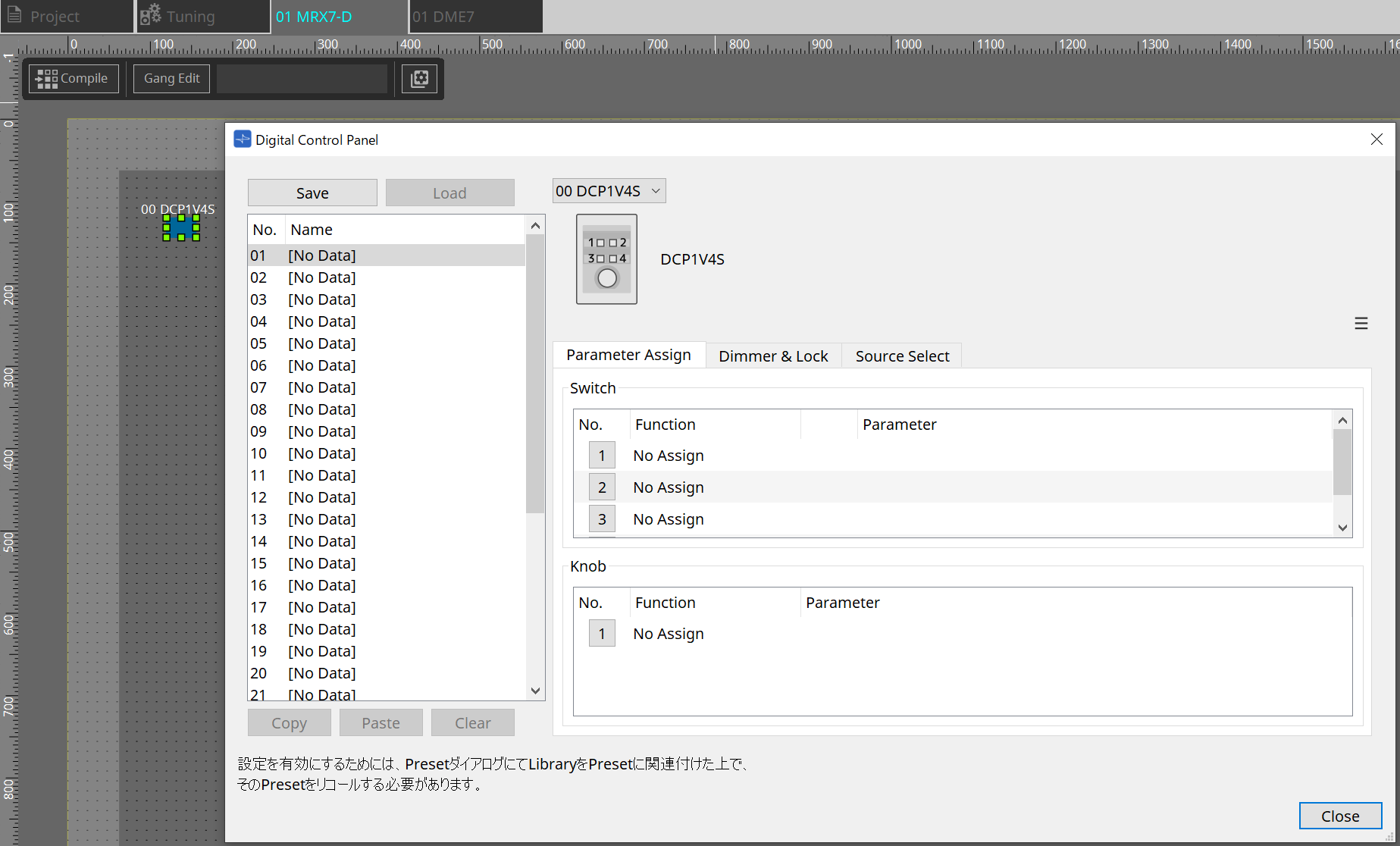
When the DCP component in MTX5-D/MTX3 is clicked, the DCP dialog opens and settings can be made.
27.4.1. DCP component settings
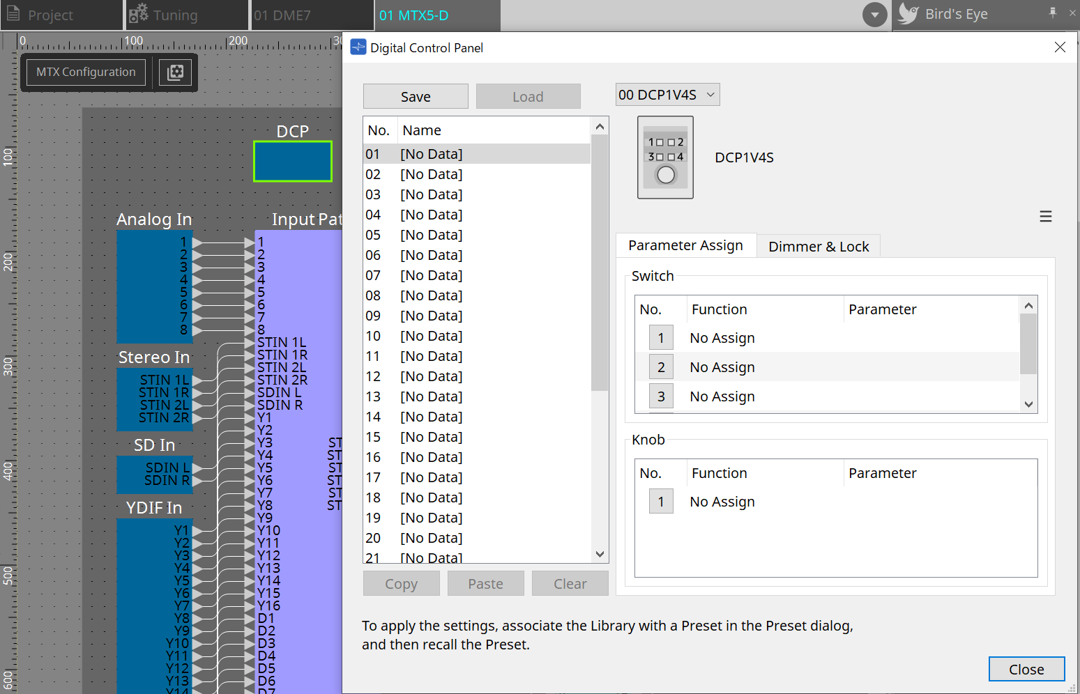
Double-click the DCP component to open the component editor.
-
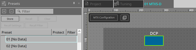
[Library]
You can store 32 sets of DCP settings in the Library.
The Library stores the settings of all DCPs connected to the MTX. Also, the DCP Library can be recalled at the same time as the MTX preset recall. Make settings in the dialog box that appears when you press the [Recall Settings] button in the “Presets” area.The library can be used on the DCP by recalling it at the same time as the MTX preset. If you want to select the DCP to recall, click the [Recall Filter] button in the “Presets” area and make filter settings in the dialog box that appears. Recalling the Library will collectively recall all DCPs (up to 8 units) connected to the MTX.
When recalling a Library, any desired DCP can be excluded from the recall.
Click on the Recall Filter button in the Presets area and set the filter in the dialog that appears.-
[Save] button
This button stores an item in the library.
The [Parameter Assign] tab and [Dimmer & Lock] tab settings will be saved. -
[Load] button
Load Library.
Expand the settings to the "Parameter Assign" tab and the "Dimmer & Lock" tab. -
[Library] list
Select the library item that you want to save or load. The currently-loaded library item is shown in bold characters.
By double-clicking a previously-saved library item, you can edit its name. -
[Copy] button
This button copies the selected library item.
The Copy command is not available while online. -
[Paste] button
This button pastes the copied library item to the library item that’s currently selected in the list. The Paste command is not available while online. -
[Clear] button
This button clears the contents of the library item that’s currently selected in the list. The Clear command is not available while online.
-
-
DCP selection box
Select the DCP unit for which you want to make settings.
The DCP set in the “Properties” area of the “Project” sheet will be displayed.
● [Parameter Assign] tab
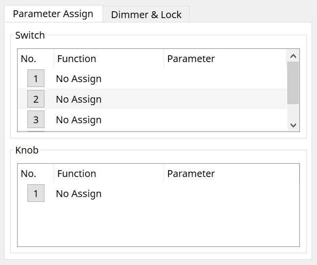
The setting dialog that is used to specify the settings for each operator is displayed when the No. icon for the operator (switch or knob) that you want to set is clicked. Assign MTX parameters to each operator in the dialog.
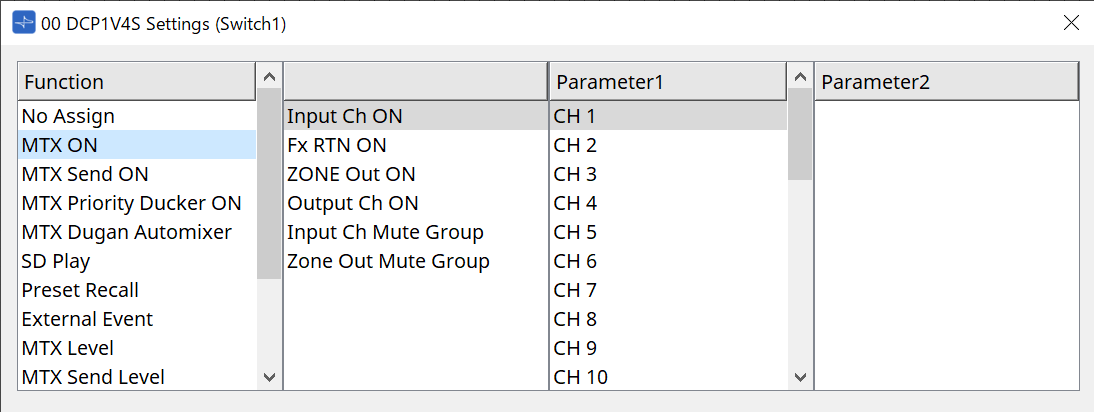
27.4.2. DCP component: Settings dialog (switch)
Click the No. icon of the DCP component editor to open it.
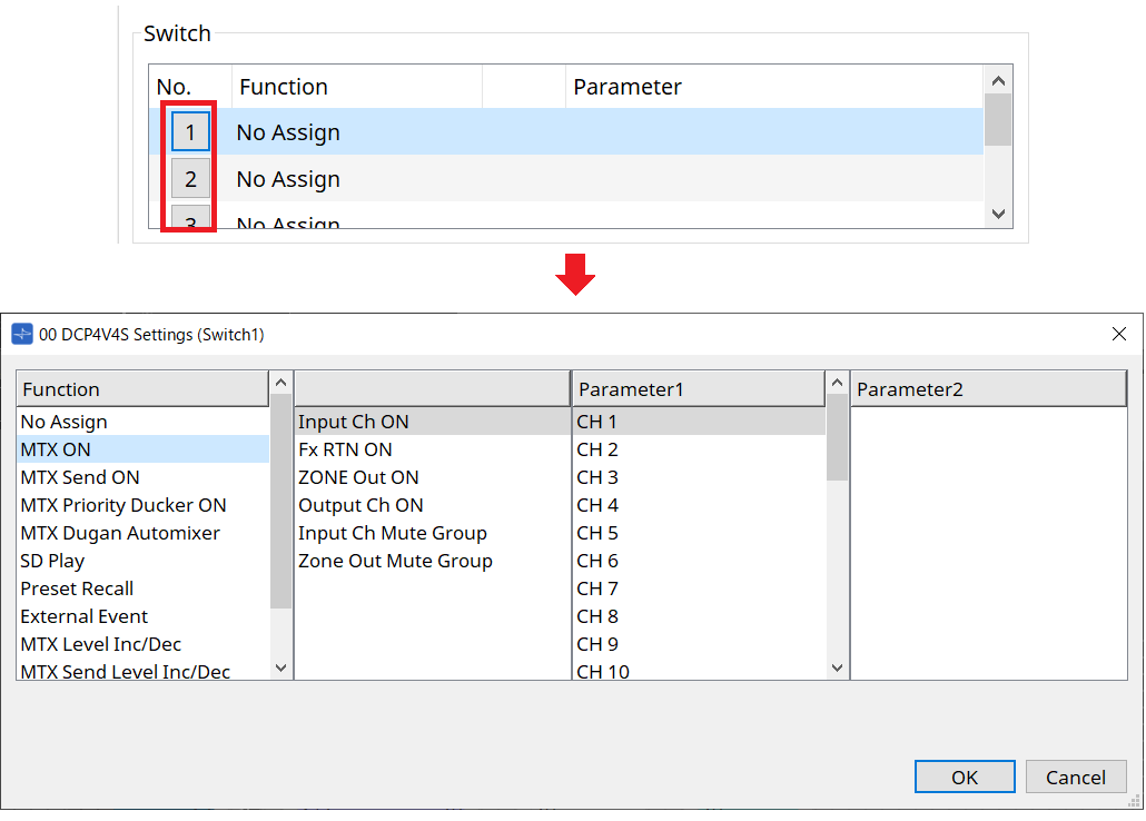
Function
-
[No Assign]
Function is not assigned. -
[MTX ON / MTX Send ON / MTX Priority Ducker ON / MTX Dugan Automixer]
Press the switch to operate the assigned parameter.
-
[SD Play]
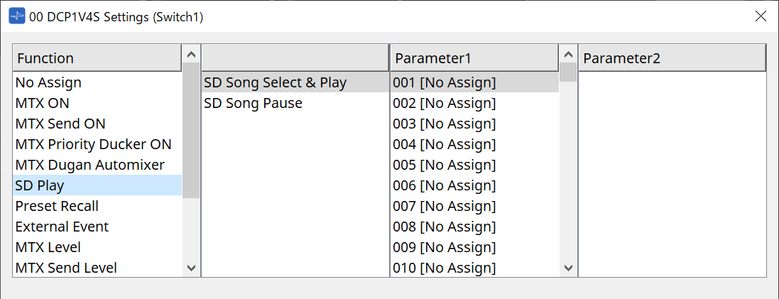
-
SD Song Select & Play
Plays the file specified in the [Parameter1] list.
Refer to "SD Card File Manager" dialog box for playback file settings. -
SD Song Pause
Press the switch to stop the file being played.
-
-
[Preset Recall]
Pressing the switch recalls the selected preset. -
[External Event]
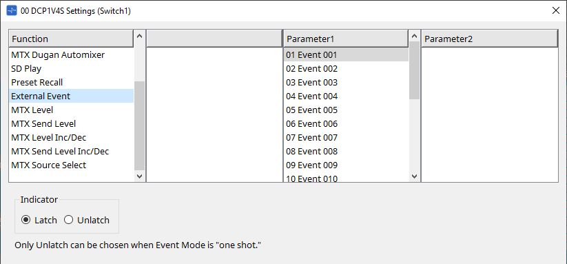
Press the switch to issue the selected event.
Set [External Event] to “External Events” dialog box .-
[Indicator]
Select whether the switch indicator will display the on/off status (Latch), or light only when the switch is pressed (Unlatch).
-
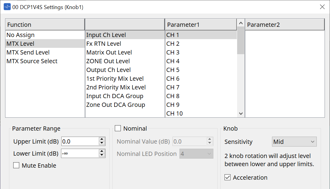
[MTX Level / MTX Send Level]
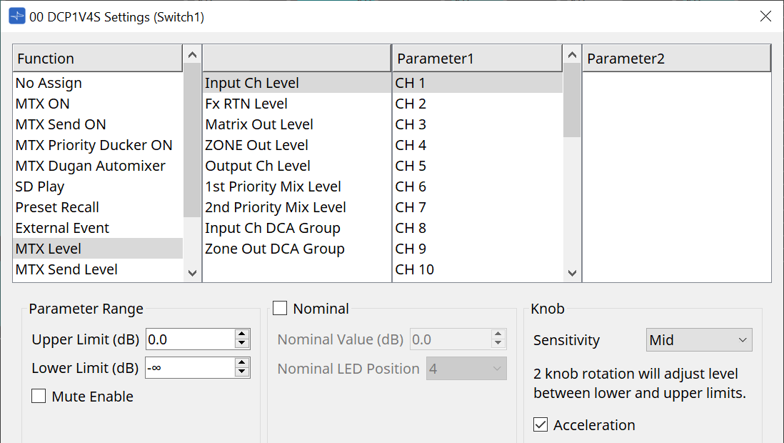
When you press the switch, the assigned parameter is automatically assigned to the knob and can be operated with the knob.
This function is only for DCP1V4S.
If you assign this to a switch, the knob will say "Occupied by sw" and will not be assignable to any other parameter. Refer to the Knob section for parameters.
[MTX Level Inc/Dec / MTX Send Level Inc/Dec]
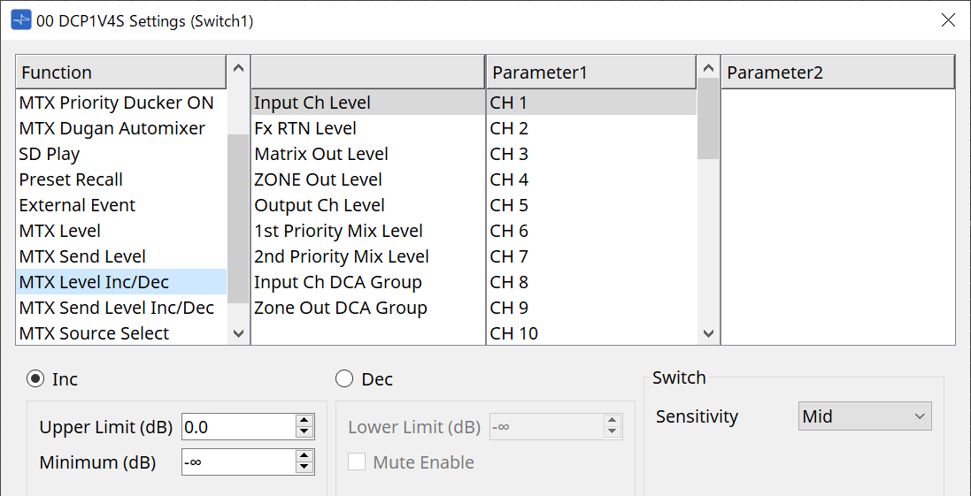
-
[Inc]
If this is selected, the value increases when the switch is pushed.
You can set the movable range with Upper Limit/Minimum. -
[Dec]
If this is selected, the value decreases when the switch is pushed.
You can set the lower limit with Lower Limit.-
[Mute Enable] check box
If this option is selected, the Mute state (–∞ dB) will be enabled if the level is lowered below the value specified by [Lower Limit].
-
-
[Sensitivity] list box
Sets the sensitivity of parameter changes in response to the downward operation of the DCP switch.
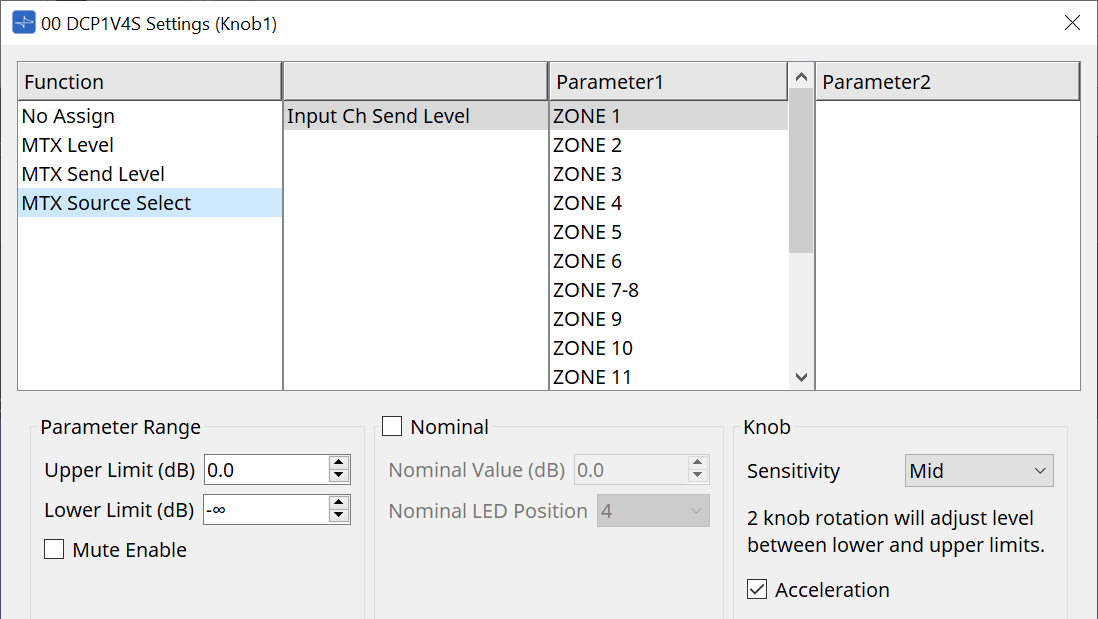
[MTX Source Select]
This is a source select function that uses the Matrix Mixer component.
Use Input Ch Send ON in combination with Input Ch Send Level.
Specify the send level to be controlled by the switch to which Input Ch Send ON is assigned, and operate that send level with the knob or switch to which Input Ch Send Level is assigned.
Input Ch Send ON
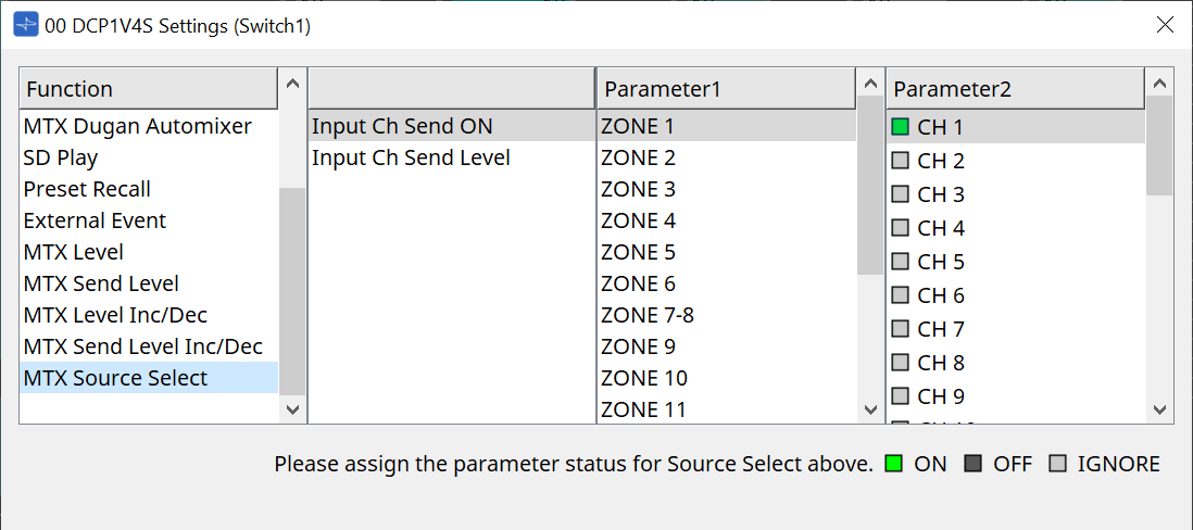
Changes the source (Parameter2) on/off for any output (Parameter1) of the Matrix Mixer component at once.
Parameter2 changes its state to "ON", "OFF", and "IGNORE" each time the checkbox is clicked.
Only one source can be turned "ON".
Example:
Assign DCP4V4S switches 1 and 2 to [MTX Source Select] > Input Ch Send ON, and knob 1 to [MTX Source Select] > Input Ch Send Level.
They all select the same output (Parameter1).

If switch 1 is pressed, the send level of CH1 for zone 1 is assigned to knob 1.

If switch 2 is pressed, knob 1 changes to CH2 send level for zone 1.

Since the switch automatically changes the send level assigned to the knob, you can control the send level of multiple points with a single knob.
Input Ch Send Level
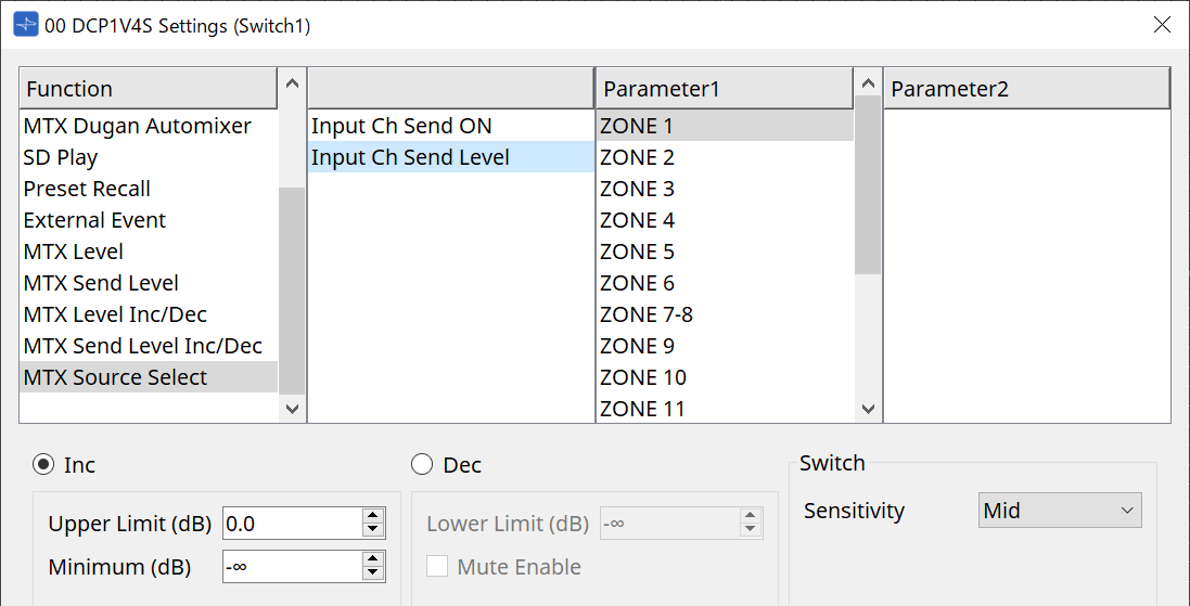
Select the output (Parameter1) of the Matrix Mixer component.
For usage, refer to [MTX Source Select] in the DCP component: Settings dialog (switch).
For parameters, refer to [MTX Level Inc/Dec/MTX Send Level Inc/Dec].
27.4.3. DCP component: Settings dialog (knob)
Click the No. icon of the DCP component editor to open it.
Function
-
[No Assign]
Function is not assigned. -
[MTX Level / MTX Send Level]
-
[Parameter Range]
Use [Upper Limit] and [Lower Limit] to specify the range in which the level can be varied.-
[Mute Enable]
If [Mute Enable] is on, the Mute state (–∞ dB) will be enabled if the level is lowered below the value specified by [Lower Limit].
-
-
[Nominal]
Here you can make settings for the Nominal function.
By specifying the nominal value, you can assign a specific LED position as the normal volume setting. For example by specifying the center LED as the volume setting for normal use and setting the maximum value to the maximum volume that is allowable for the system, you can prevent damage to the system that might occur if the volume of the background music were raised during a noisy time.
If the check box is selected, the Nominal function will be on.
[Nominal Value] specifies the nominal value.
[Nominal LED Position] specifies the LED position that will light when the level reaches the nominal value.
If the check box is cleared (Nominal function off), both parameters will be grayedout and unavailable.-
[Sensitivity] list box
Sets the sensitivity of parameter changes in response to the rotary operation of the DCP knob.
If [Acceleration] is on, the parameter will change faster if the knob is rotated more rapidly. If [Fast] is selected as the [Sensitivity], the [Acceleration] setting is dimmed and unavailable.
-
-
[MTX Source Select]
For usage, refer to [MTX Source Select] in the DCP component: Settings dialog (switch).
For parameters, refer to [MTX Level / MTX Send Level].
●
[Dimmer & Lock] tab
This sets the brightness of the LEDs on the DCP unit and the settings for the resting state.
-
[LED Brightness] list box
Specifies the brightness of the DCP unit’s LEDs. Higher values will make the LEDs brighter. -
[Enable Inactive Mode] check box
If the check box is selected, the unit automatically enters inactive mode after a time duration specified in [Waiting Time].
[Inactive LED Brightness] specifies the brightness of the LEDs when inactive.
If the check box is cleared, the drop-down menu is grayed-out and you will be unable to set the brightness. -
[Panel Lock] check box
If this check box is selected, the DCP panel will be locked when the preset library is recalled.
If the [Enable Temporary Unlocking] check box is selected, pressing and holding down DCP switch 1 for two seconds will unlock the panel. -
[Waiting Time]
Specifies the time from the last operation until the unit enters inactive mode or the panel is locked.
Menu button
Click this button to execute the following functions.
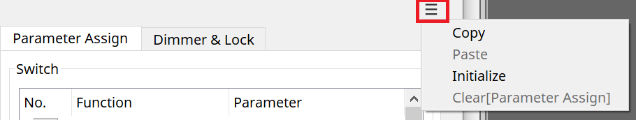
-
[Copy]
Copies the Parameter Assign, Dimmer & Lock, and Source Select of the displayed DCP to the copy buffer. -
[Paste]
Overwrites the Parameter Assign, Dimmer & Lock, and Source Select settings of the same model from the copy buffer onto the displayed DCP.
It is only possible to paste settings that were copied within the same MTX system. -
[Initialize]
Initializes the Parameter Assign, Dimmer & Lock, and Source Select settings of the displayed DCP. -
[Clear [Parameter Assign]]
Initializes the Parameter Assign settings of the displayed DCP.
[Close] button
Closes the dialog box.
27.5. MRX7-D Setting Method
Double-click the DCP component and configure various settings.
For other operations, refer to the MTX5-D/MTX3 DCP Component Settings .
27.5.1. DCP Component Settings
Double-click the DCP component to open the component editor.
[Library]
Up to 32 DCP-related settings can be saved as a [Library].
The Library stores the settings for all DCPs connected to the MRX7-D.
| The Library can be used on the DCP itself by recalling it at the same time as the MRX7-D presets. Configure the settings in the dialog that appears when the [Recall Settings] button in the Presets area is pressed. |
|
When the Library is recalled, all DCPs (up to 8 units) connected to the MRX7-D will be recalled at once.
When recalling a Library, any desired DCP can be excluded from the recall. Click on the [Recall Filter] button in the Presets area and set the filter in the dialog that appears. |
For other operations, refer to the MTX5-D/MTX3 DCP Component Settings .
27.5.2. [Parameter Assign] Tab
27.5.2.1 Settings Dialog (Switch)
Click the No. icon in the DCP component editor to display the Settings dialog.
Refer to the DME7
Settings Dialog (Switch)
.
The differences compared to the DME7 are listed below.
[Snapshot Recall]
[Snapshot Group Recall]
[Preset Recall]
| Registration Source | Registration Method |
|---|---|
|
Parameter Sets Area |
Drag & drop the snapshot into the green area of the Settings dialog.
|
|
Presets Area |
Drag & drop the preset into the green area of the Settings dialog. |
[Parameter]
| Registration Source | Registration Method |
|---|---|
|
Component Editor |
While holding the < Ctrl > key down, drag & drop the parameter into the green area of the Settings dialog. |
|
Link Control Editor |
While holding the < Ctrl > key down, drag & drop the Link Control into the green area of the Settings dialog. |
|
Parameters Area |
Drag & drop the parameter into the green area of the Settings dialog. |
| [Control Type] cannot be set. |
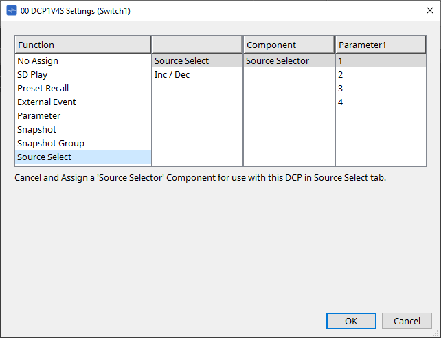
[MRX Source Select]
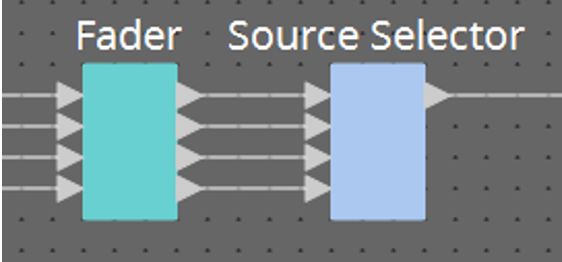
This function allows you to change the source of the Source Selector component using the switch, and to change the levels related to the source using the knob. Use a configuration that combines the Source Selector component and Fader component.
Assign Function: Source Selector to both the switch and the knob.
Procedure
-
Add a Fader component and a Source Selector component to the device sheet and connect them.
-
Select one of the Source Selector components being placed in the Source Select tab of the DCP component editor.
-
Assign the source for the Source Selector component to the switch.
-
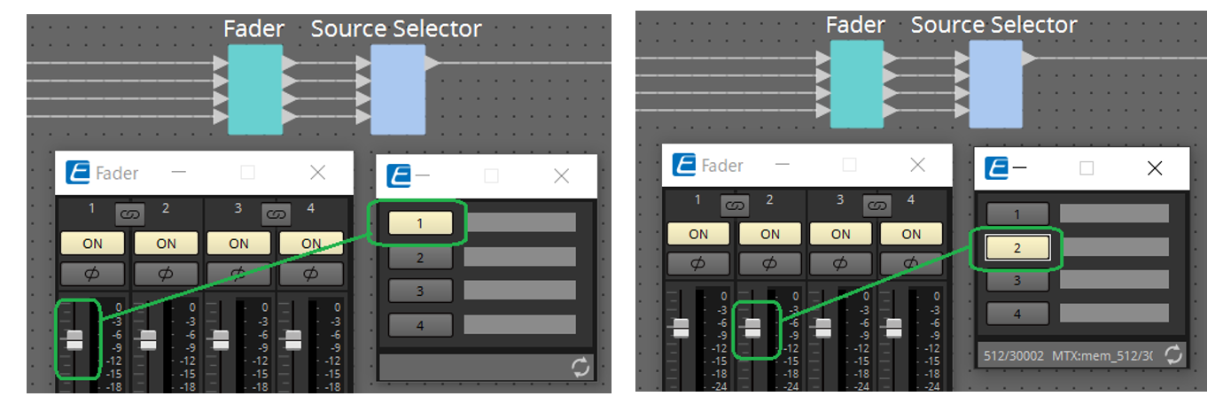
Assigns the level for the fader component connected to the Source Selector component to the knob.
When a source is selected, assign the level parameter output from the Source Selector component by dragging & dropping it into the green area. Set for each source.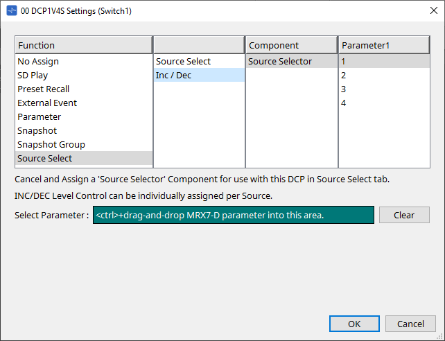
For example, if you select source 1 with switch 1, 1Ch of the Fader component will be assigned to knob 1, and if you select source 2 with switch 2, 2Ch of the Fader component will be assigned to the same knob 1.
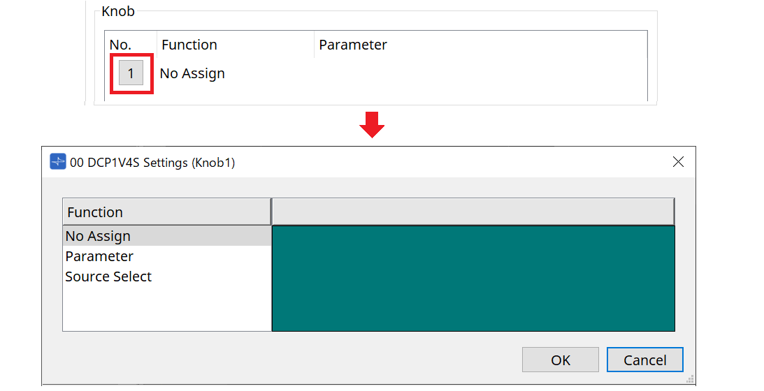
27.5.2.2 Settings Dialog (Knob)
Click the No. icon in the DCP component editor to display the Settings dialog.
Refer to the DME7
Settings Dialog (Knob)
.
The differences compared to the DME7 are listed below.
[Parameter]
| Registration Source | Registration Method |
|---|---|
|
Component Editor |
While holding the < Ctrl > key down, drag & drop the parameter into the green area of the Settings dialog. |
|
Link Control Editor |
While holding the < Ctrl > key down, drag & drop the Link Control into the green area of the Settings dialog. |
|
Parameters Area |
Drag & drop the parameter into the green area of the Settings dialog. |
[MRX Source Select]
Refer to MRX Source Select in "Settings Dialog (Switch)."
27.5.3. [Dimmer & Lock] Tab
Refer to the MTX5-D/MTX3 Dimmer & Lock Tab .
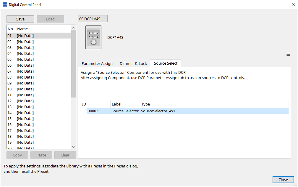
27.5.4. [Source Select] Tab
Select one of the Source Selector components placed on the device sheet.
For a description of the functions, refer to "Settings Dialog (Switch)."