Wall-mount Controller: MCP1
28. Wall-mount Controller: MCP1
28.1. Overview
The MCP1 is a wall-mounted control panel for controlling device parameters, presets, etc.
The External Event function allows products that are not supported by ProVisionaire Design to be controlled.
A home page and six pages can be set, and up to 36 parameters can be assigned to the switches.
Please also refer to the MCP1 Installation Manual for information on handling the MCP1.
28.2. Project Sheet
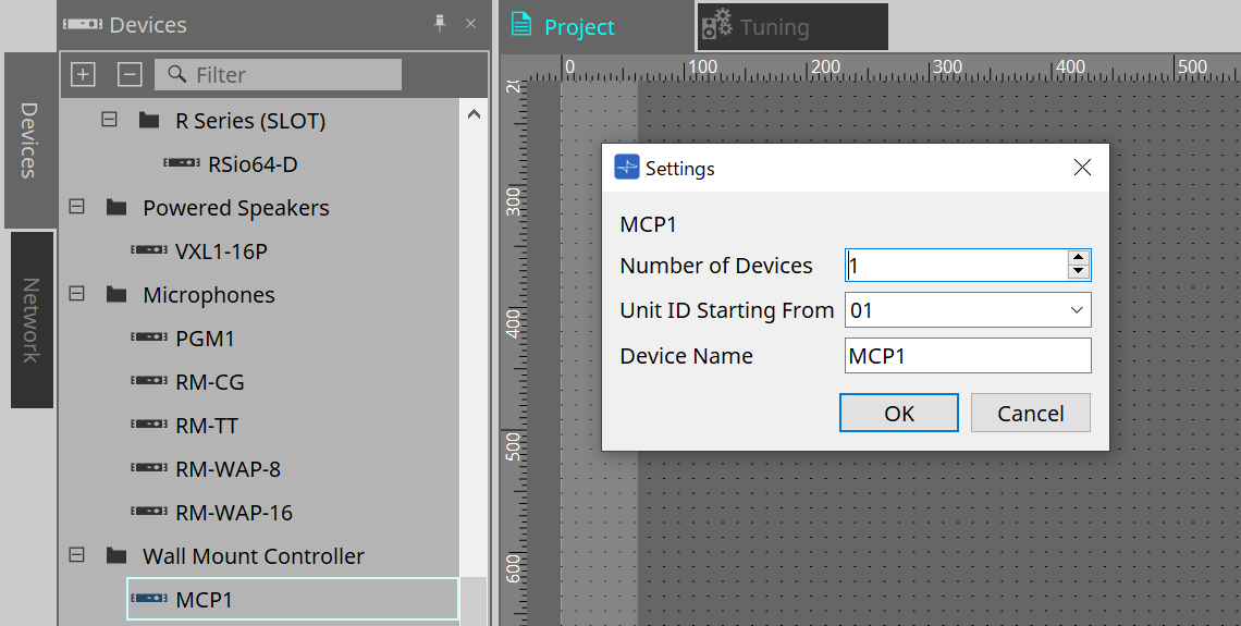
This is the sheet on which devices are placed. When placing devices, the Settings screen shown below is displayed.
-
Number of Devices
Selects the number of MCP1 units to be placed on the sheet. -
Unit ID Starting From
The starting number for the device Unit IDs can be selected. -
Device Name
The device name can be displayed and edited.
28.2.1. Properties Area
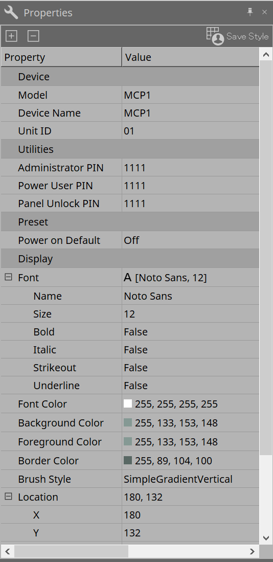
Displays/edits the MCP1 information.
-
Utilities
-
Administrator PIN
This is the code to open the Settings Page on the main unit. It is a four-digit number.
It can also be used as the Power User PIN and Panel Unlock PIN. -
Power User PIN
This is the code to open the page when "Power User Page (PIN required)" is enabled. It is a four-digit number. -
Panel Unlock PIN
This is the code to unlock the panel lock. It is a four-digit number.
-
28.3. Setting Method
-
Double-click the MCP1 placed on the Project sheet.
Component Editor will be displayed.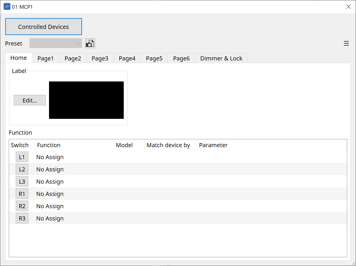
-
Click on the [Controlled Devices] button in the Component Editor.
The Controlled Devices dialog will be displayed.
On this screen, register the devices to be controlled by the MCP1.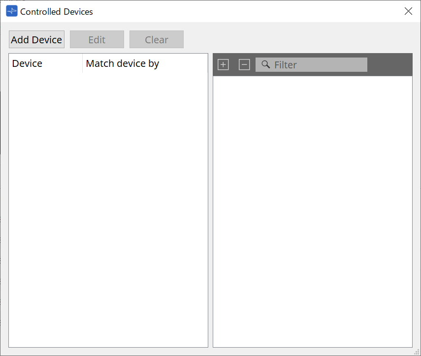
For devices with fixed configurations, such as the MTX5-D and PC-D series, the device does not necessarily need to be placed on the Project sheet.
However, devices such as the DME7 and MRX7-D, whose configurations can be freely changed by the user, must be placed on the Project sheet. This is to assign parameters by dragging and dropping them from the Component Editor of the device sheet, the Parameter Sets area, etc.
-
Click on the [Switch Selection Button] in the Component Editor.
The Settings dialog will be displayed.
-
Drag and drop parameters from the parameter list in the Controlled Devices dialog to the Settings dialog to assign them to switches.
For the DME7 and MRX7-D, drag parameters from the Component Editor or the Parameters area.
Even if you move to the DME7 or MRX7-D device sheet, the Settings dialog will remain displayed.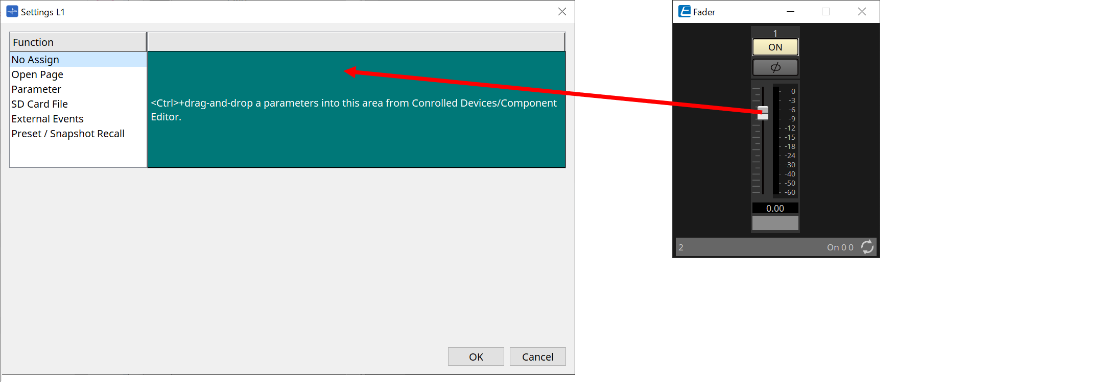
Refer to the Settings dialog for information on how to assign parameters.
| To control a product that is not supported by ProVisioniare Design, use Function > External Event. |
-
Click on the [Preset] button.
The Preset List dialog will be displayed. Presets save all page and Dimmer & Lock settings.
Loading a preset will load the page and Dimmer & Lock settings into the MCP1 Editor. If you recall a preset while online, the panel settings on the MCP1 main unit will also change.
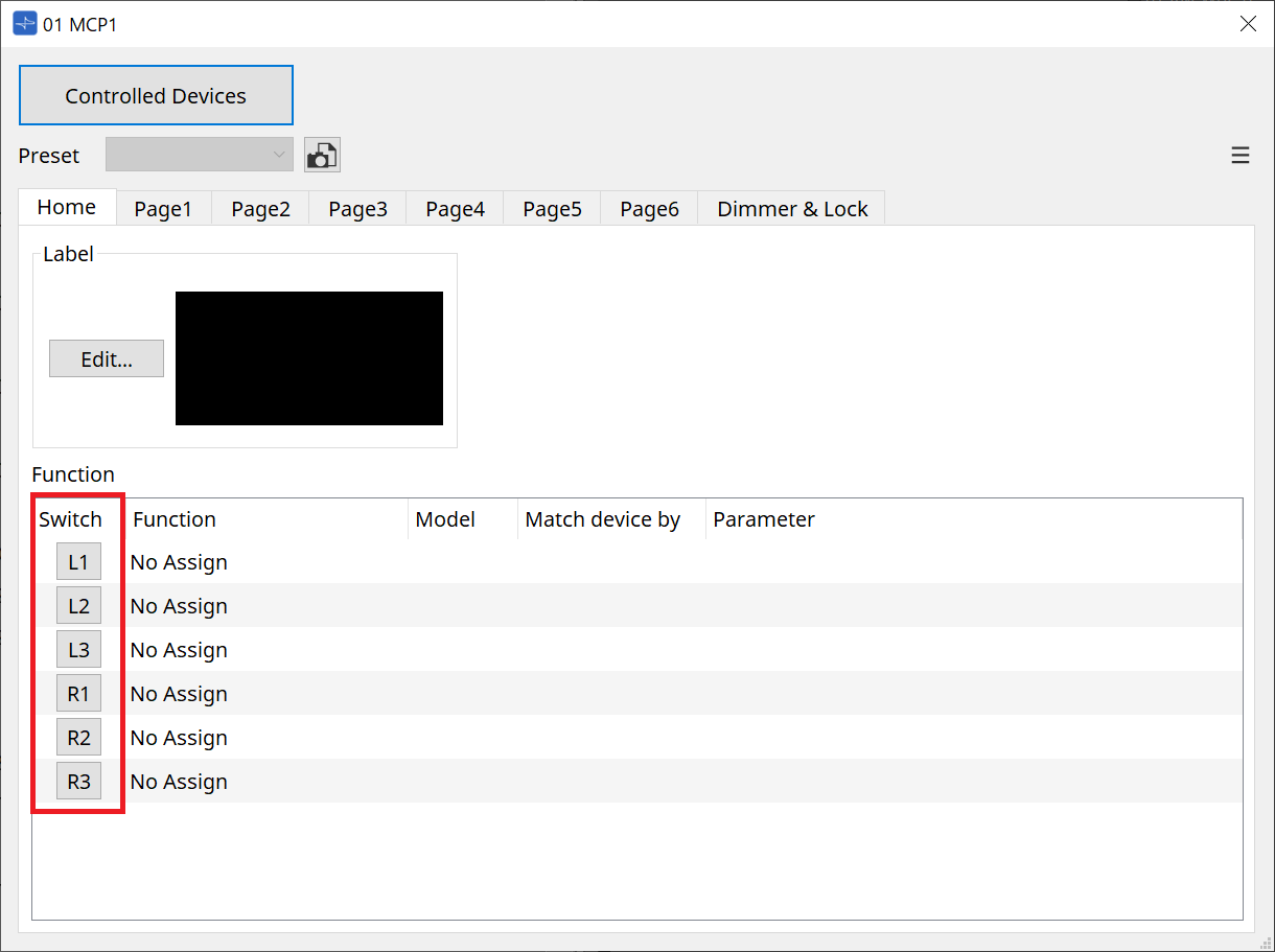
28.4. Component Editor
Double-clicking a device on the Project sheet will open the editor.

①
[Controlled Devices] Button
Opens the
Controlled Devices dialog
.
②
Preset list
Recalls presets.
③
[Preset] Button
Opens the
Preset List dialog
.
④
[Home]/[Page 1] to [Page 6] tabs
Set the MCP1 pages.
The [Home] page is the page that is displayed when the MCP1 is started up or the Home switch is pressed.
On the [Home] page, you can switch pages by assigning [Open Page] to a switch.
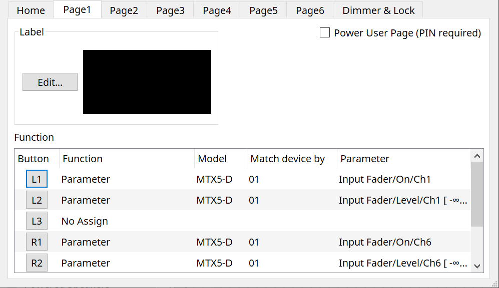
The [Page 1] tab will be explained here.
-
[Power User Page [PIN required]] checkbox (other than [Home] page)
If checked, you will be required to enter the Power User PIN when opening a page on the MCP1 main unit.
The Power User PIN is set in the device’s Properties area > Utilities.
⑤
Label [Edit] Button
Opens the
Label dialog
.
⑥
Function [Switch] selection button
Click to open the
Settings dialog
.
⑦
[Function]/[Model]/[Match device by][Parameter]
Displays an overview of the settings made on the Settings screen.
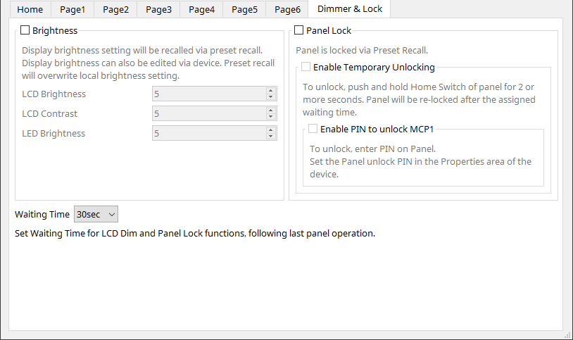
28.4.1. [Dimmer & Lock] Tab
Sets the brightness of the MCP1’s display and switches, and the operation of the panel lock.
-
[Brightness] checkbox
If this box is checked, the brightness and contrast of the display and the brightness of the switches can be changed when a preset is recalled.
[LCD Brightness] is the brightness of the display. The higher the number, the brighter the display will be.
[LCD Contrast] is the contrast of the display. The higher the number, the greater the difference between brightness and darkness.
[LED Brightness] is the brightness of the switches. The higher the number, the brighter the switches will be. -
[Panel Lock] checkbox
If this box is checked, the MCP1 panel will be locked when a preset is recalled. If the [Enable Temporary Unlocking] box is checked, the panel can be unlocked by pressing and holding the Home switch on the MCP1 for longer than 2 seconds.
If the [Enter PIN to unlock MCP1] box is checked, you will be prompted to enter the Panel Unlock PIN when unlocking the panel. -
[Waiting Time]
Sets the time from the last operation until the MCP1 enters hibernation or a locked state.
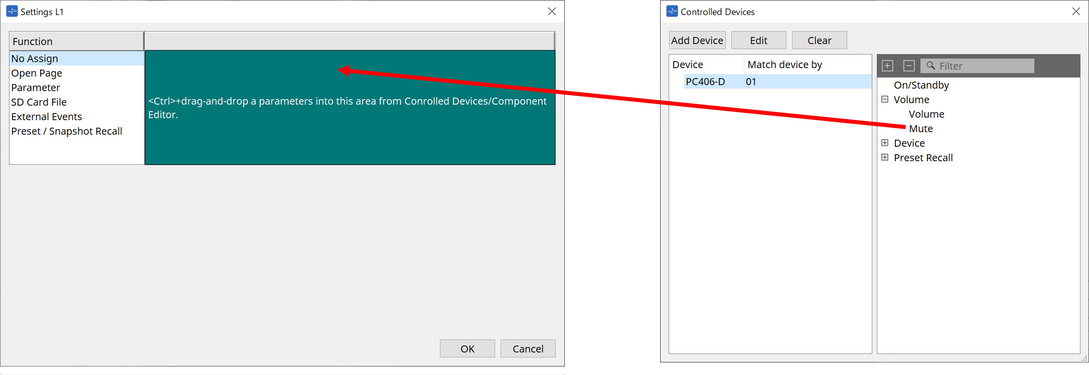
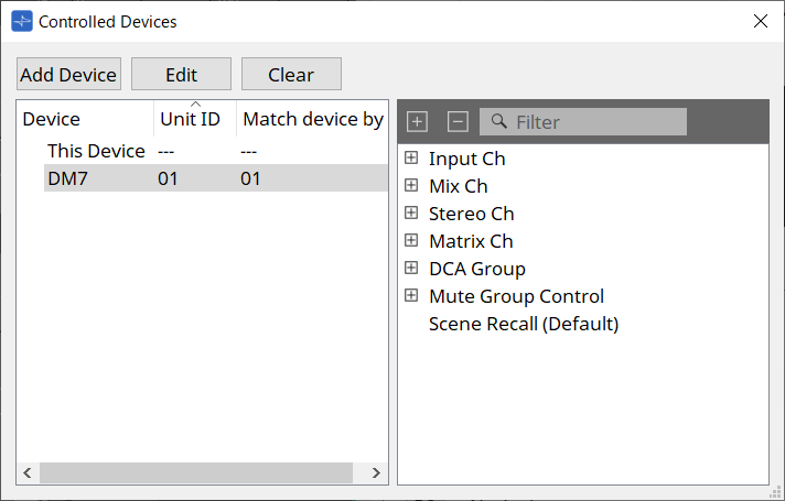
28.4.2. Controlled Devices Dialog
Displayed when the [Controlled Devices] button in the
Component Editor
is clicked.
Register the devices to be controlled by the MCP1.
-
[Add Device] Button
Click to open the Add Device dialog.
Register the devices to be controlled by the MCP1.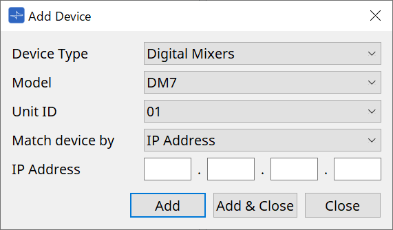
Selects how the MCP1 searches for devices on the network in [Match Device by].
Select [IP Address] to search by device IP address, or select [Unit ID] to search by device Unit ID.
| Unit ID can be used as a device identifier when adding devices to a sheet. |
-
[Edit] Button
Click to open the Unit ID & Match Device by dialog.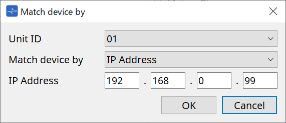
Changes the [Unit ID] and [Match Device by] of the device selected in the Device List.
-
[Clear] Button
Deletes the device selected in the Device List. -
Device List
Displays the registered devices. -
Parameter List
Displays the parameters of the device selected in the Device List.
Parameters can be registered in the Settings dialog by dragging and dropping them.
| Register parameters for models whose configurations can be freely changed, such as the DME7 and MRX7-D, by dragging and dropping them from the Component Editor or the Parameters area to the Settings dialog. |
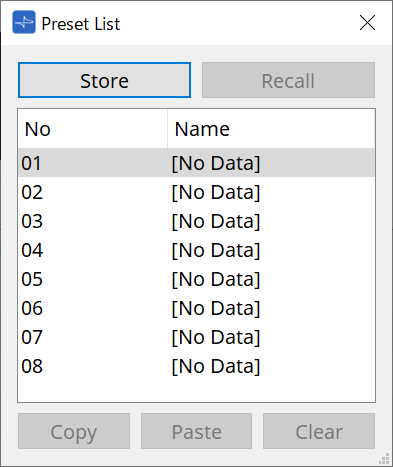
28.4.3. Preset List Dialog
Up to eight MCP1-related settings can be saved as presets.
Presets can be recalled from external devices. They can also be recalled with other MCP1 switches.
-
[Store] Button
Saves the [Home]/[Page 1] to [Page 6]/[Dimmer & Lock] settings to a preset. -
[Recall] Button
Recalls the selected preset.
The settings are expanded to [Home]/[Page 1] to [Page 6]/[Dimmer & Lock].
If you recall a preset while online, the panel settings on the main unit will also change. -
[Copy] Button
Copies the selected preset. -
[Paste] Button
Pastes the copied preset to the selected preset. -
[Clear] Button
Clears the selected preset.
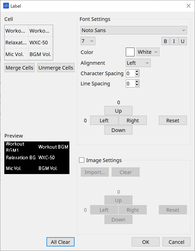
28.4.4. Label Dialog
Creates an image for each page to be displayed on the MCP1 main unit’s display.
-
[Cell]
Edits the page screen.
To edit text, double-click the cell or select the cell and press the < F2 > key.
Press the < Enter > key or use the mouse to select another cell to confirm.
If including a background image in a cell, select the cell and check the [Image Settings] checkbox. Press the [Import] button and select the image file.
Cells can be moved not only with the mouse, but also with the cursor keys, < Tab > key, and < Enter > key.
A range of cells can also be selected by moving through them while holding down the < Shift > key. -
[Merge Cells] Button
Select multiple cells and click this to merge them. -
[Unmerge Cells] Button
Select merged cells and click this to unmerge them. -
[Preview]
Displays the page image.
The text and images set in [Cell] can be checked. -
Font Settings Area
Sets the font of the text displayed in the selected cell.-
Font List Box
Selects a font. Fonts installed on the computer can be selected. -
Font Size List Box
Selects the font size. -
[B]/[I]/[U] Buttons
Click to make the text in the cell bold/italicized/underlined. -
Color
Displays the color of the text in the cell. Click on the button to switch between white and black. -
[Alignment] List Box
Selects the alignment of the text in the cell. -
[Character Spacing] spin box
Sets the spacing between characters in a cell. -
[Line Spacing] spin box
Sets the spacing between rows in a cell. -
[Up]/[Left]/[Right]/[Down]/[Reset] Buttons
Adjust the text position in the cell. The amount of movement is displayed as a numerical value. Click on the [Reset] button to restore it to the initial value.
-
-
Image Settings
The background image of the selected cell can be set when this is checked.-
[Import] Button
Click to open the Open File dialog.
The selectable image extensions are .png , .bmp, and *.jpg.
After selecting the image data, click on the [OK] button to open the Re-size Image dialog where you can select how to arrange the image in the cell.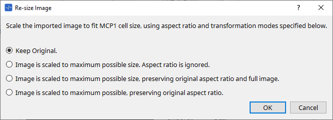
-
[Clear] Button
Click to delete the background image. -
[Up]/[Left]/[Right]/[Down]/[Reset] Buttons
Adjust the background image position in the cell. The amount of movement is displayed as a numerical value. Click on the [Reset] button to restore it to the initial value.
-
-
[All Clear] Button
Initializes all cell information. -
[OK] Button
Retains the setting information and closes the dialog. -
[Cancel] Button
Discards the setting information and closes the dialog.
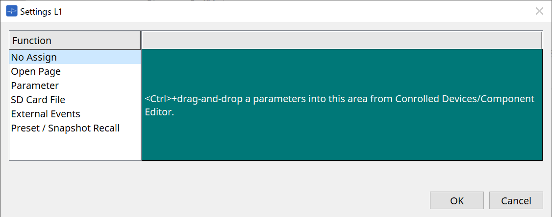
28.4.5. Settings dialog
Registers parameters and presets to be controlled by the MCP1.
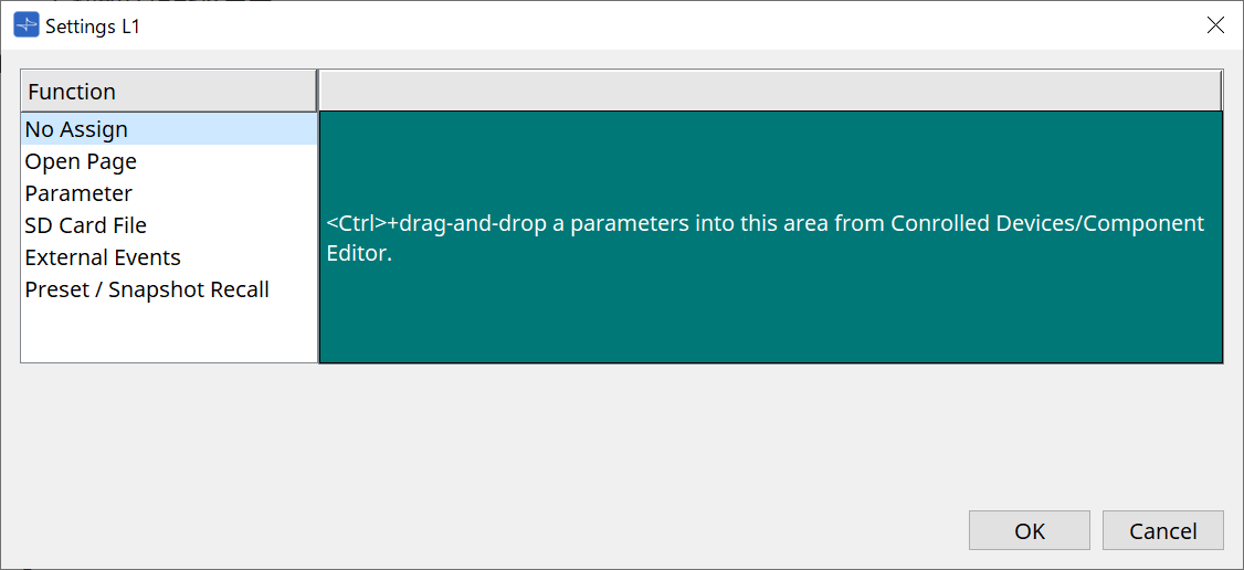
Parameters and presets can be registered to switches by dragging and dropping them into the green area.
| Registration Source | Registration Method |
|---|---|
|
Parameter List in the Controlled Device dialog |
Drag and drop the parameter or preset into the green area of the Settings dialog. |
|
DME7 and MRX7-D Component Editor*1 |
While holding down the < Ctrl > key, drag and drop the parameter into the green area of the Settings dialog. |
|
DME7 and MRX7-D Parameters Area |
Drag and drop the parameter into the green area of the Settings dialog. |
|
MRX7-D Link Control Editor |
While holding down the < Ctrl > key, drag and drop the Link Control into the green area of the Settings dialog. |
|
DME7 Parameter Sets Area |
Drag and drop the snapshot into the green area of the Settings dialog. |
|
MRX7-D Parameter Sets Area |
Drag and drop the snapshot into the green area of the Settings dialog.
|
|
MRX7-D Presets Area |
Drag and drop the preset into the green area of the Settings dialog. |
*1 For devices other than the DME7 and MRX7-D, parameters can only be registered from the Parameter List in the Controlled Device dialog.
Function
-
[No Assign]
Function is not assigned.
-
[Open Page (Home page only)]
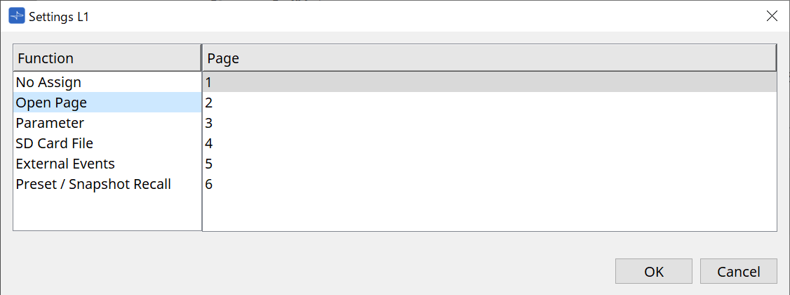
Press the switch to change the MCP1 page.
-
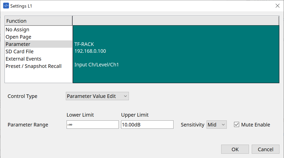
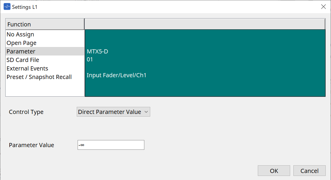
[parameter]
-
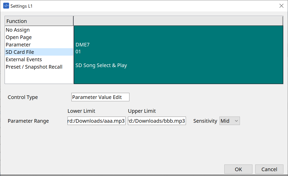
Control Type list box
When Parameter Value Edit is selected
Operates the assigned parameter within the range specified by the Lower Limit and Upper Limit.
Select the parameter you want to operate on the MCP1 main unit by touching it, and operate it using the L1/2/3 and R1/2/3 switches and return switch.
-
Parameter Range
Sets the parameter’s range of motion.
Click Lower Limit/Upper Limit to display the controls. -
Mute Enable checkbox
When this is turned on, a Mute state (–∞ dB) occurs when the level falls below the value set in [Lower Limit]. -
[Sensitivity]
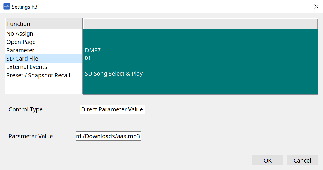
Sets the sensitivity with which the parameter changes in response to switch operations.When Direct Parameter Value is selected
Sets the assigned parameter to the value specified by Value.
Click Parameter Value to display the controls.
-

-
[SD Card File Manager]
For DME7/MRX7-D or MTX3/MTX5-D placed on the Project sheet
When SD Card File > Sel & Play is assigned from Controlled Devices, the SD Card File Manager dialog starts.
For the DME7, one file or multiple consecutive files can be selected.
For the MTX3, MTX5-D, and MRX7-D, only one file can be selected.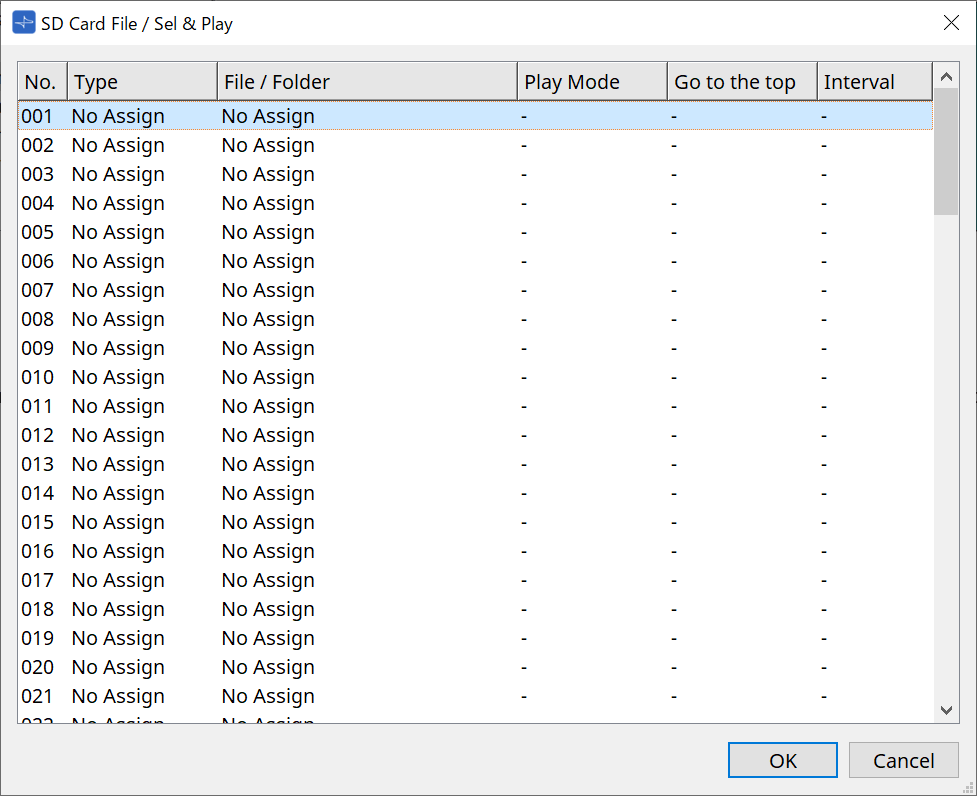
For the DME7, multiple files can be selected.
When multiple files are selected (for DME7 only)

When one file is selected

For MTX3/MTX5-D not placed on the Project sheet
After assigning SD Card File > Sel & Play from Controlled Devices by dragging and dropping it, configure the settings related to file playback.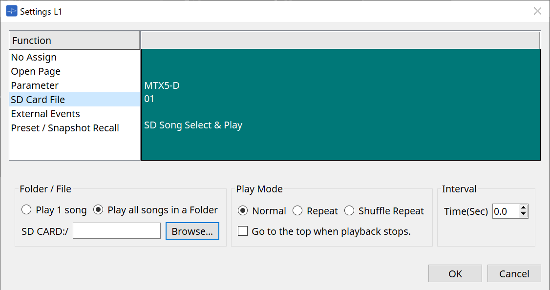
Refer to the DME7 SD Card File Manager dialog for setting details.
-
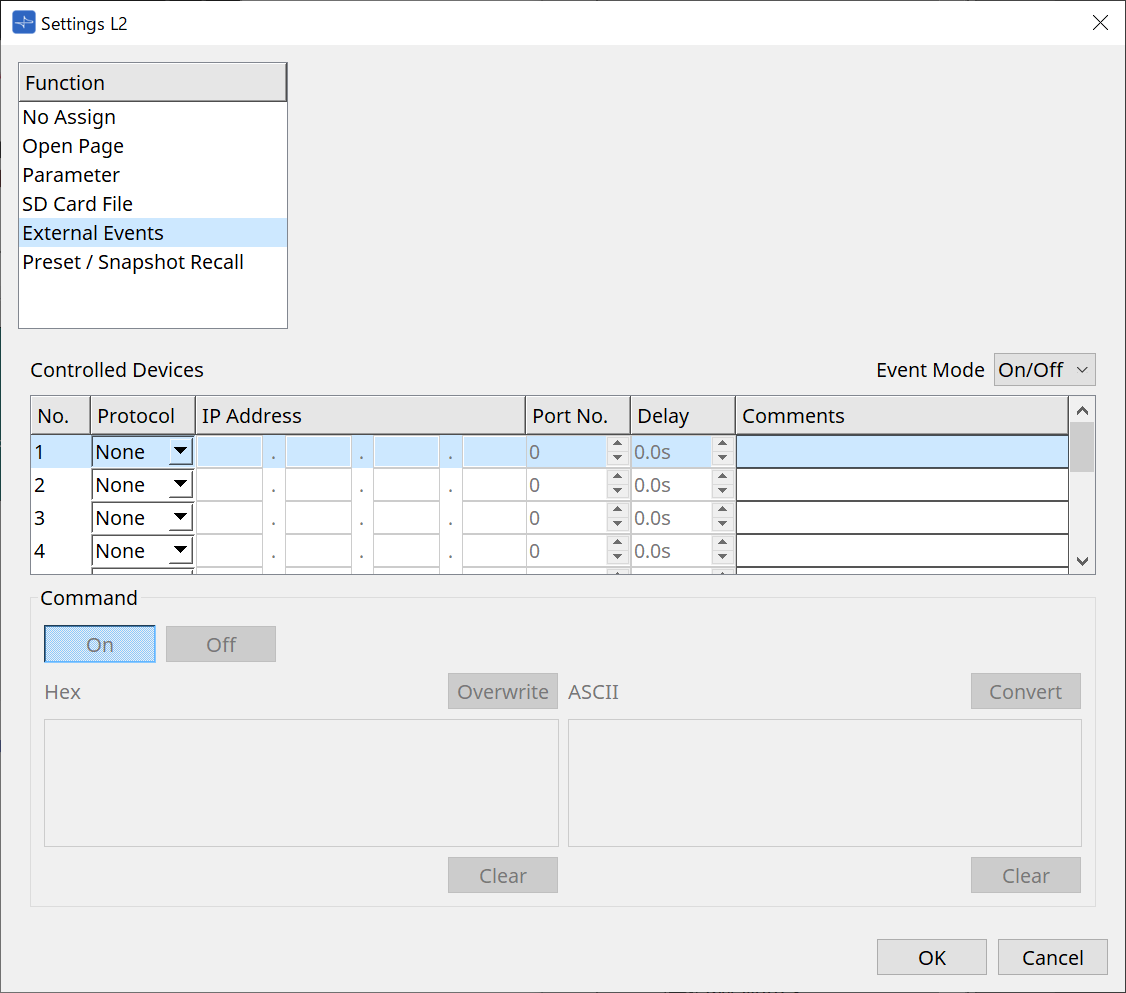
[External Event]
-
[Event Mode] List Box
When an event is assigned to a switch, it operates as follows.
[On/Off]: The MCP1 alternately sends an On command and Off command each time the switch is pressed.
[1shot]: The MCP1 sends the set command each time the switch is pressed. -
Controlled Device
Sets the information for the device receiving commands.
For details on how to configure the receiving device, refer to the documentation for each device’s commands.-
Protocol
Selects the protocol supported by the device receiving commands. -
IP Address
Set the IP address of the device receiving commands. -
Port No.
Sets the port number of the device receiving commands. -
Delay
Sets the delay for each command, with the time the switch was pressed as 0. -
Comments
Allows for input of text.
-
-
Command On/Off
Displayed when set to On/Off in the [Event Mode] list box.
Sets the respective commands when the switch is on and off.
Commands are entered in two-digit hexadecimal format.-
Overwrite/Insert
When set to [Insert], input in the Command text box becomes an insert, and hexadecimal numbers can be added at the beginning or in the middle. -
Hex
Sets the command to control the device in hexadecimal. -
Clear
Deletes the command. -
Ascii
If commands to control the device are provided as character strings in the specifications, etc., enter the commands and use the [Converter] button to convert them into hexadecimal. -
[Convert] Button
Converts commands in character strings into hexadecimal and enters them in "Hex".
-
-
-
[Presets/Snapshots]
-
Control Type
When Parameter Value Edit is selected
Sequentially numbered presets or snapshots can be assigned to a single device.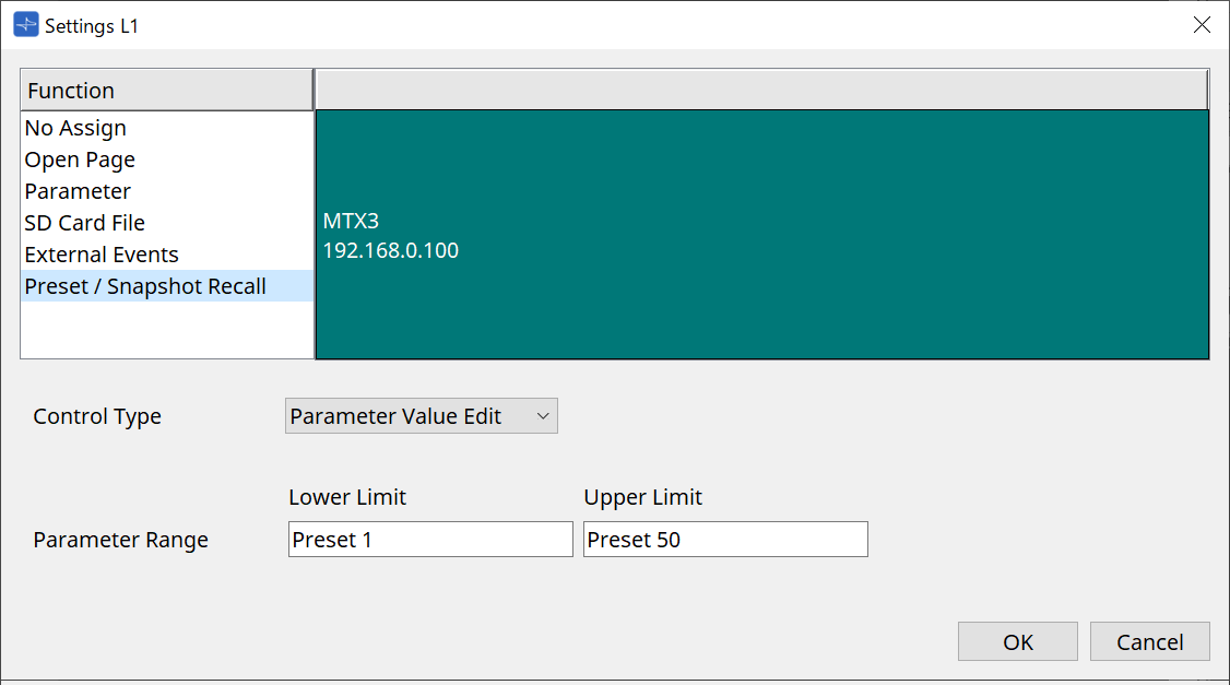

When Direct Parameter Value is selected
Multiple presets, snapshots, or snapshot groups can be assigned to the same switch at the same time by repeating the assign operation. Presets for different devices can also be assigned at the same time.For the Rivage PM series and DM7 series, only the Direct Parameter Value can be selected. For the MRX7-D snapshot group, only the Direct Parameter Value can be selected. 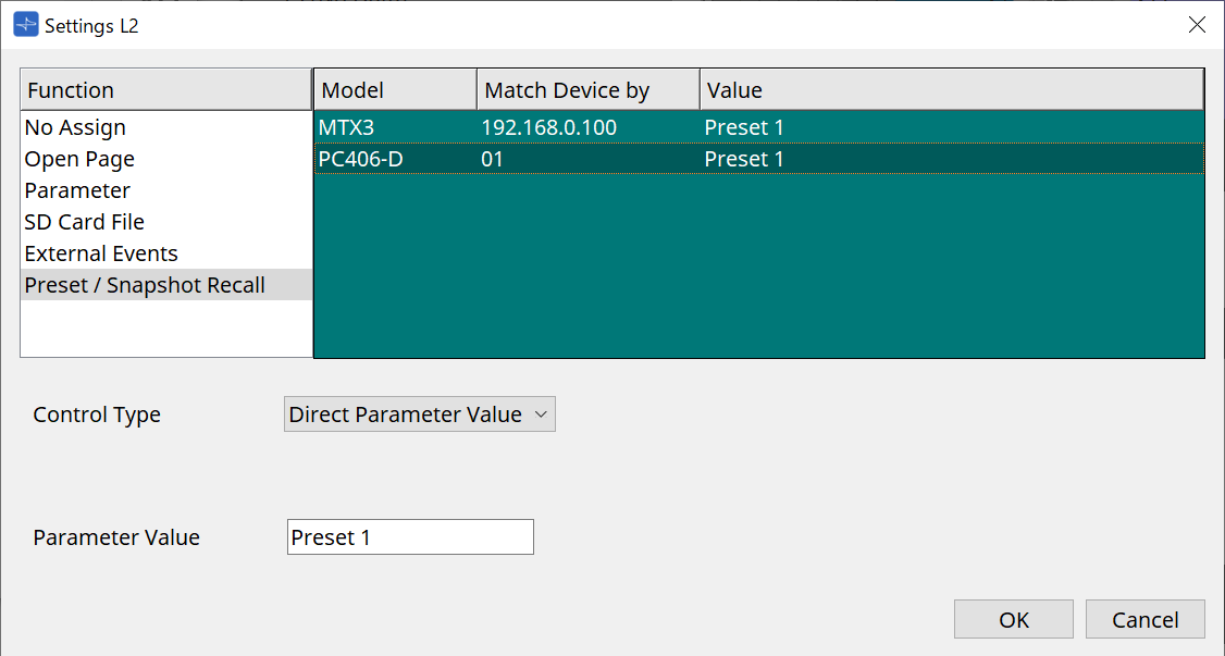

-
28.5. Alert List
Refer to the MTX5-D/MTX3 Alert List .