On the Osc/Tune screen, you can set the Oscillator for the Element.
Here, you can select the Waveform used as the basis for the sound and set the key range and velocity range of the Element.
- [PERFORMANCE] → [EDIT/
] → Part selection → Element selection → Osc/Tune
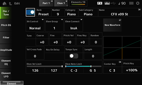
Sets the selected Element on or off. Settings: Off, On
Number (Waveform Number)
Category (Waveform Category)
Sub Category (Waveform Sub Category)
Name (Waveform Name)
Shows the name of the Waveform selected for the Element.
Bank indicates the type of Waveform (Preset, User, and Library) assigned to the Element. Settings: Refer to the Data List.
XA (Expanded Articulation) is a function for creating realistic sounds like those on acoustic instruments as well as creating new synth sounds.
You can create such sounds by setting the XA Control to specify the way the Element is played.
- Creating smooth legato
Make the Element alternate between one element with XA Control set to Normal and another element with the XA Control set to Legato. - Producing sounds when releasing fingers from the keys.
Create an Element with XA Control set to Key Off. - Creating randomness for the same note
Make the Element with XA Control set to Cycle and another one with XA Control set to Random. - Producing sounds unique to acoustic instruments
Some examples of sound unique to acoustic instruments include harmonics and palm mute on the guitar, flutter-tonguing on the flute, and growl on the saxophone.
Set up an Element with XA Control set to A.Sw1 On or A.Sw2 On, or A.Sw Off, and control from the [ASSIGN 1] and [ASSIGN 2] buttons on the top panel.
The [ASSIGN 1] and [ASSIGN 2] buttons can be set to On or Off by sending the Control Change number set in the Control → Control Number of the Common Edit screen from an external device.
Settings: Normal, Legato, Key Off, Cycle, Random, A.Sw1 On, A.Sw2 On, A.Sw Off
Normal: Played as a normal Element.
Legato: Played when Mono/Poly is set to Mono. When you play in Legato, the Element set to Legato will be played instead of the Element set to Normal.
Key Off: Played when a finger is lifted off from the key.
Cycle: Played when there are a series of Elements set in Cycle.
Random: Plays the Elements randomly when multiple Elements are set to Random.
A.Sw Off: Played when both [ASSIGN 1] and [ASSIGN 2] buttons are set to Off.
A.Sw1 On: Played when the [ASSIGN 1] button is set to On.
A.Sw2 On: Played when the [ASSIGN 2] button is set to On.
This parameter is for sorting Elements having the same XA Control setting into groups.
When XA Control of all Elements is set to Normal, this setting is not effective. Settings: 1–8
Sets the output of the Element to Insertion Effect A or Insertion Effect B.
Setting it to Thru bypasses the Insertion Effects. Settings: Thru, InsA, InsB
Loads the audio file saved on the USB flash drive as a Waveform.
Edit Waveform appears when a Waveform is loaded.
Opens the Waveform Edit screen.
Shifts the pitch of the Element in semitones. Settings: −48–+48
Finely adjusts the pitch of the Element. Settings: −64–63
Sets how the pitch change responds to Velocity or the strength of the keystroke. Settings: −64–63
Positive value: Faster Velocity values produce a higher pitch.
Negative value: Faster Velocity values produce a lower pitch.
0: No change in pitch.
Sets how the pitch change in the Fine Tuning responds to the position of the key. Settings: −64–63
Positive values: The pitch goes down when you press a key in the bass section, and the pitch goes up when you press a key in the treble section.
Negative values: The pitch goes up when you press a key in the bass section, and the pitch goes down when you press a key in the treble section.
Changes the pitch of the Element randomly each time a key is pressed.
Set the parameter to a larger value to create more pitch changes. When the value is set to 0, the pitch is kept unchanged. Settings: 0–127
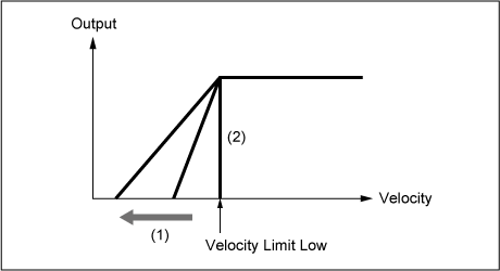
Sets the output level of the Oscillator to become lower as keystroke Velocity values become further from the value set in Velocity Limit.
When set to 0, no sound is produced if the velocity is outside the Velocity Limit. The larger the value, the more gradually the way the output level of the Oscillator decreases. Settings: 0–127
Sets the timing of the Key On Delay to synchronize with the tempo. Settings: Off, On
Sets the delay time from when the key is pressed to when sound is produced.
This parameter is not available when Tempo Sync is set to On. Settings: 0–127
This parameter is available when Tempo Sync is set to On. You can set the timing for Key On Delay by using musical notes. Settings: 1/16 (sixteenth notes), 1/8 Tri. (eighth-note triplets), 1/16 Dot. (dotted sixteenth notes), 1/8 (eighth notes), 1/4 Tri. (quarter-note triplets), 1/8 Dot. (dotted eighth notes), 1/4 (quarter notes), 1/2 Tri. (half-note triplets), 1/4 Dot. (dotted quarter notes), 1/2 (half notes), Whole Tri. (whole-note triplets), 1/2 Dot. (dotted half notes), 1/4 × 4 (quarter-note quadruplets; four quarter notes to the beat), 1/4 × 5 (quarter-note quintuplets; five quarter notes to the beat), 1/4 × 6 (quarter-note sextuplets; six quarter notes to the beat), 1/4 × 7 (quarter-note septuplets; seven quarter notes to the beat), 1/4 × 8 (quarter-note octuplets; eight quarter notes to the beat)
Sets the velocity range (lowest and highest values) for playing the Element wave.
When this is set so that the higher value is first and the lower value is second (for example, 93 to 34), the Element sounds only for velocities of 1 to 34 and 93 to 127. Settings: 1–127
Sets the note range (lowest and highest notes) for the Element.
When the first note specified is higher than the second (for example, C5 to C4), the Element is played in the ranges C−2 to C4 and C5 to G8. Settings: C−2–G8
Sets the reference note for Pitch/Key (Pitch Key Follow Sensitivity).
The key set with the note number here is played at the normal pitch regardless of the Pitch/Key setting. Settings: C−2–G8
Sets the difference in pitch between two adjacent keys. The reference point is the key specified in Center Key.
This parameter is useful for playing unpitched sounds, such as special effects, or for playing a percussion instrument as a Normal Part, or for any other cases where the pitch difference does not have to be in semitones.
Settings: −200%–+0%–+200%
+100% (normal setting): Pitch difference between the two keys next to each other is set to a semitone.
0%: No pitch difference between the two keys, and all keys are played at the pitch set in Center Key.
Negative value: Sets an opposite pitch response such that lower notes result in higher pitch, and higher notes result in lower pitch.
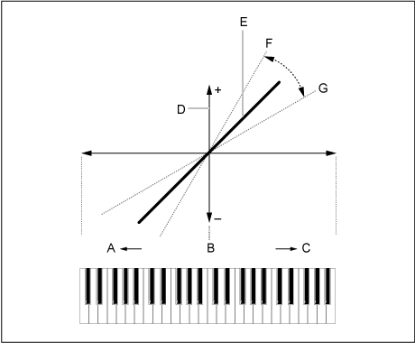
A: Lower notes
B: Center Key
C: Higher notes
D: Difference in pitch
E: When Pitch/Key (Pitch Key Follow Sensitivity) is set to +100%.
F: Larger
G: Smaller
Opens the Waveform Edit screen.
Here, you can set the various Key Banks that make up a Waveform.
A Key Bank is digital data comprised of a short audio segment, such as vocals or other sounds, loaded into the instrument. It has the same characteristics as a wav file; however, to avoid confusion a different name is used to distinguish it from the Waveform.
Key Banks are always saved as a part of a Waveform.
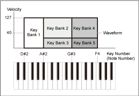
One Waveform is capable of holding multiple Key Banks. You can save even a few dozen Key Banks, for example, in one Waveform. If you are saving multiple Key Banks in one waveform, you can assign a key range and velocity range for each Key Bank by specifying the Note Limit and Velocity Limit. By setting up multiple Key Banks, you can play various Key Bank sounds depending on the section of the keyboard you use and the strength of your keystroke.
Example of Key Bank and Waveform setup
A Waveform must be loaded into a Part before it can be played.
You can assign a Waveform to an AWM2 Part from Element Edit in Part Edit (AWM2), or to a Drum Part from Key Edit in Drum Part Edit (AWM2).
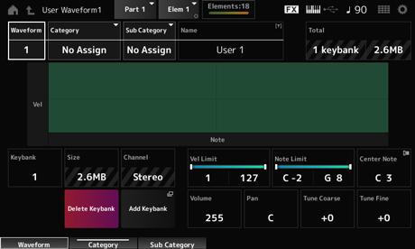
Shows the name of the selected Waveform.
Sub Category (Waveform Sub Category)
Sets the Main category and Sub category of the selected Waveform. Settings: Refer to the Data List.
You can save the Waveform you are editing under a new name, using up to 20 alphanumeric characters. Tapping on the name calls up the onscreen keyboard, allowing you to enter a name.
Shows the number of Key Banks in the waveform and the total size of the data capacity.
Shows the Key Bank number.
Shows the total size of data capacity.
Shows whether the Key Bank is stereo or mono.
Sets the velocity range (lowest and highest values) for playing the Key Bank. Settings: 1–127
Sets the note range (lowest and highest notes) for playing the Key Bank. Settings: 1–127
Sets the key (pitch) of the original waveform data. Settings: C−2–G8
Sets the volume of the Key Bank. Settings: 0–255
Sets the Pan position (in the stereo field) of the Key Bank. Settings: L63 (left)–C (center)–R63 (right)
Shifts the pitch of the Key Bank in semitones. Settings: −64–+63
For fine pitch adjustment of the Key Bank. Settings: −64–+63
Deletes the Key Bank.
Adds a Key Bank to the waveform.
The Pitch EG screen lets you set the Envelope Generator for the Oscillator.
By setting the PEG (Pitch Envelope Generator) time and level (the amount of pitch change), you can set how the sound changes from the moment you press a key on the keyboard to when the sound decays to silence.
- [PERFORMANCE] → [EDIT/
] → Part selection → Element selection → Pitch EG
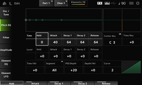
Sets the length of time it takes for keeping the pitch at Hold Level starting from the moment you press a key on the keyboard. Settings: 0–127
Sets the length of time it takes for the pitch to change from the end of the Hold Time to the Attack Level. Settings: 0–127
Sets the length of time it takes for the pitch to change from the Attack Level to the Decay 1 Level. Settings: 0–127
Sets the length of time it takes for the pitch to change from the Decay 1 Level to the Decay 2 Level. Settings: 0–127
Sets the length of time it takes for the pitch to change from the moment you release the key until it reaches the Release Level. Settings: 0–127
Sets the pitch level for the moment you press the key. Settings: −128–+127
Sets the pitch to change from the Hold Level or the moment you press a key. Settings: −128–+127
Sets the next pitch value to change from the Attack Level. Settings: −128–+127
Sets the next pitch value to change from the Decay 1 Level. Settings: −128–+127
Sets the final pitch to reach after you have released the key. Settings: −128–+127
Sets the reference note (or a key to press) for Time/Key.
With the note (key) set here, the resulting sound of the pitch change set in PEG is played. Settings: C−2–G8
Sets how the pitch change speed of the PEG responds to the position of the key.
The change speed in PEG is used for the specified key in Center Key. Settings: −64–+63
Positive value: The higher the key pressed, the faster the pitch changes of the PEG.
Negative value: The higher the key pressed, the slower the pitch changes of the PEG.
0: No PEG changes regardless of the key position.
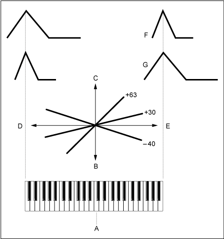
A: Center Note
B: Slow
C: Fast
D: Low key
E: High key
F: Positive value
G: Negative value
Segment (PEG Time Velocity Sensitivity Segment)
Sets how the pitch change speed of the PEG responds to Velocity or the strength of the keystroke.
First, set the time value in Segment and then set the velocity sensitivity value in Time/Vel. Settings: Time/Vel: −64–+63
Positive value: The faster the velocity, the faster the changes in the PEG.
Negative value: The faster the velocity, the slower the changes in the PEG; slow velocities result in faster PEG changes.
0: No PEG changes regardless of the velocity setting.
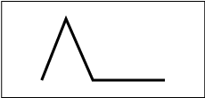
Fast velocity (pitch change is fast)
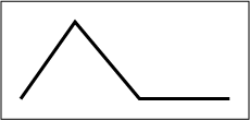
Slow velocity (pitch change is slow)
Settings: Segment: Attack, Atk+Dcy, Decay, Atk+Rls, All
Attack: Time/Vel value affects the Attack Time.
Atk+Dcy: The Time/Vel value affects the Attack Time and Decay 1 Time.
Decay: The Time/Vel value affects the Decay Time.
Atk+Rls: The Time/Vel value affects the Attack Time and Release Time.
All: The Time/Vel value affects the time-related settings in PEG.
Sets the depth range of pitch changes controlled by the PEG. Settings: −64–+63
0: No pitch change.
The further the depth is from a value of 0, the wider the pitch change becomes.
Negative value: Pitch change is inverted.
Curve (PEG Depth Velocity Sensitivity Curve)
Sets how the depth range of the pitch change controlled by the PEG responds to Velocity or the strength of the keystroke.
Also, with the Curve setting, you can set how the PEG Depth responds to the velocity. The vertical axis represents velocity while the horizontal axis represents the depth range of the pitch changes. Settings: Depth/Vel: −64–+63
Positive value: Fast velocity widens the depth range of the PEG, while slow velocity narrows the depth range.
Negative value: Fast velocity narrows the depth range of the PEG, while slow velocity widens the depth range.
0: No PEG changes regardless of the velocity setting.
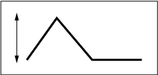
Fast velocity
(the depth range in pitch change is wider)
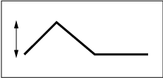
Slow velocity
(the depth range in pitch change is narrower)
Settings: Curve: 0–4

On the Type screen, you can select a filter type for the Element.
The available parameters differ depending on the filter type you have selected here.
- [PERFORMANCE] → [EDIT/
] → Part selection → Element selection → Filter → Type
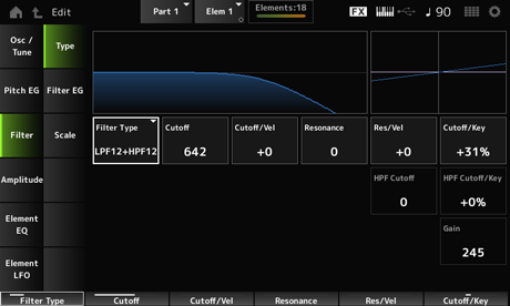
Sets the filter for the Element.
The filters available on this instrument are grouped into four types: LPF, HPF, BPF, and BEF.
Settings: LPF24D, LPF24A, LPF18, LPF18s, LPF12+HPF12, LPF6+HPF12,
HPF24D, HPF12, BPF12D, BPFw, BPF6, BEF12, BEF6, DualLPF, DualHPF, DualBPF, DualBEF, LPF12+BPF6, Thru
This Filter Type cuts the signals above the value set in Cutoff Frequency.
The sound becomes brighter as you raise the Cutoff Frequency, because more high-frequency signals are passed by the filter; conversely, it becomes darker as you lower the Cutoff Frequency, because more high-frequency signals are cut or blocked by the filter. You can produce a distinctive “peaky” sound by raising the Resonance or boosting the signal level near the Cutoff Frequency.
This Filter Type is very popular and useful for producing classic synthesizer sounds.

LPF24D: A dynamic −24 dB/oct Low-Pass Filter with a characteristic digital sound. Compared to the LPF24A type, this filter can produce a more pronounced Resonance effect.
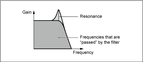
LPF24A: A digital dynamic Low-Pass Filter with characteristics similar to a 4-pole analog synthesizer filter.
LPF18: 3-pole −18 dB/oct Low-Pass Filter.
LPF18s: 3-pole −18 dB/oct Low-Pass Filter. This filter has a smoother cutoff slope than the LPF18 type.
This Filter Type only passes signals above the Cutoff Frequency.
You can produce a distinctive “peaky” sound by raising the Resonance or boosting the signal level near the Cutoff Frequency.
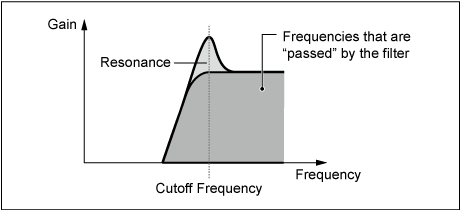
LPF12+HPF12: A combination of a −12 dB/oct Low-Pass Filter and a −12 dB/oct High-Pass Filter connected in serial. When this Filter Type is selected, HPF Cutoff and HPF Key Follow Sensitivity can be set.
LPF6+HPF12: A combination of a −6 dB/oct Low-Pass Filter and a −12 dB/oct High-Pass Filter connected in serial. When this Filter Type is selected, HPF Cutoff and HPF Key Follow Sensitivity can be set.
HPF24D: A dynamic −24 dB/oct High-Pass Filter with a characteristic digital sound. This filter can produce a pronounced Resonance effect.
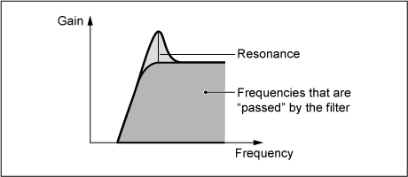
HPF12: −12 dB/oct dynamic High-Pass Filter.
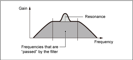
This Filter Type that only passes signals for a specific frequency band (Cutoff Frequency) and cuts all other signals.
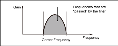
BPF12D: The combination of a −12 dB/oct HPF and LPF with a characteristic digital sound.
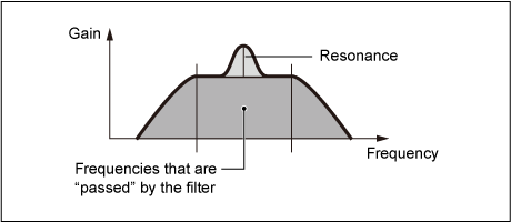
BPFw: A −12 dB/oct BPF that combines HPF and LPF filters to allow wider bandwidth settings.
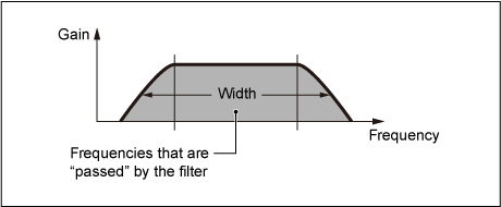
BPF6: The combination of a −6 dB/oct HPF and LPF.
The Band-Eliminate Filter has an opposite effect on the sound compared to the Band-Pass Filter.
When this Filter Type is selected, you can set the Cutoff Frequency around which the audio signal is muted or eliminated.
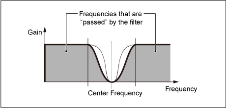
BEF12: −12 dB/oct Band-Eliminate Filter.
BEF6: −6 dB/oct Band-Eliminate Filter.
DualLPF: Two −12 dB/oct Low-Pass Filters connected in parallel. You can edit the distance between the two Cutoff Frequencies. The result of the filter is shown on the screen.
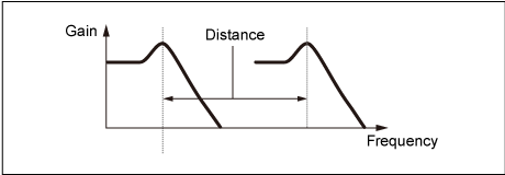
Lower Cutoff Frequency is set directly on the display
(and Higher Cutoff Frequency is automatically set)
DualHPF: Two −12 dB/oct High-Pass Filters connected in parallel.
DualBPF: Two −6 dB/oct Band-Pass Filters connected in parallel.
DualBEF: Two −6 dB/oct Band-Eliminate Filters connected in serial.
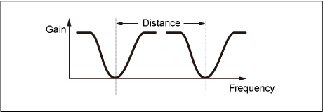
Lower Cutoff Frequency is set directly on the display
(and Higher Cutoff Frequency is automatically set)
LPF12+BPF6: A combination of a −12 dB/oct Low-Pass Filter and a −6 dB/oct Band-Pass Filter connected in parallel. You can edit the distance between the two Cutoff Frequencies.
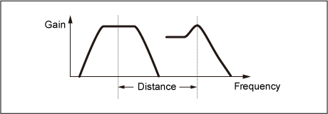
Lower Cutoff Frequency is set directly on the display
(and Higher Cutoff Frequency is automatically set)
Sets the Cutoff Frequency.
The frequency set here is used by the filter set in Type. Settings: 0–1023
Sets how the Cutoff Frequency responds to Velocity or the strength of the keystroke. Settings: −64–+63
Positive values: The faster the Velocity, the higher the Cutoff Frequency value becomes.
Negative values: The slower the Velocity, the higher the Cutoff Frequency value becomes.
0: No changes for the Cutoff Frequency by Velocity.
Width (Filter Width)
The parameter shown here varies depending on the Filter Type setting. Resonance is shown for LPF, HPF, BPF (excluding BPFw), or BEF, and Width is shown for BPFw.
For Resonance, this parameter indicates the strength of resonance. This can be used in combination with the Cutoff parameter to add further character to the sound.
For the BPFw, this parameter is used for adjusting the width of the frequencies passed by the filter.
This parameter may not be available depending on the Filter Type. Settings: 0–127
Sets how the resonance level responds to Velocity or the strength of the keystroke.
This parameter may not be available depending on the Filter Type.
Settings: −64–+63
Positive value: The higher the Velocity, the greater the Resonance becomes.
Negative value: The lower the Velocity, the greater the Resonance becomes.
0: Resonance value does not change.
Sets how the Cutoff Frequency level of the filter responds to key position.
The reference point is the Cutoff Frequency for the key set in Center Key. Settings: −200%–+200%
Positive values: The lower the key played, the lower the Cutoff Frequency becomes; the higher the key played, the higher the Cutoff Frequency becomes.
Negative values: The lower the key played, the higher the Cutoff Frequency becomes; the higher the key played, the lower the Cutoff Frequency becomes.
Sets the distance between the Cutoff Frequencies for the Dual Filter types and the LPF12+BPF6 filter.
This parameter may not be available depending on the Filter Type. Settings: −128–+127
Sets the center frequency for the functions that control the filter cutoff and how fast the FEG changes according to the key follow setting of HPF.
Increasing the value results in a higher Cutoff Frequency, and the low frequency signals are cut or blocked to make the sound brighter. Decreasing the value results in a higher Cutoff Frequency, and the low frequency signals are passed to make the sound deeper.
This parameter is not available when the Filter Type is set to LPF12+HPF12 or LPF6+HPF12. Settings: 0–1023
Sets the level of the Cutoff Frequency of the high-pass filter according to the position of the key.
This parameter is not available when the Filter Type is set to LPF12+HPF12 or LPF6+HPF12. Settings: −200%–+200%
Positive values: The lower the key played, the lower the Cutoff Frequency becomes; the higher the key played, the higher the Cutoff Frequency becomes.
Negative values: The lower the key played, the higher the Cutoff Frequency becomes; the higher the key played, the lower the Cutoff Frequency becomes.
Sets the Gain (signals sent to the Filter unit).
Lowering the value decreases the volume of the Element. Settings: 0–255
On the Filter EG screen, you can set the Filter Envelope Generator (FEG) for the Element.
The FEG lets you set the degree (or level) of changes to the Cutoff Frequency and how those changes evolve over time, starting from the moment you press a key on the keyboard to the moment the sound decays.
- [PERFORMANCE] → [EDIT/
] → Part selection → Element selection → Filter → Filter EG
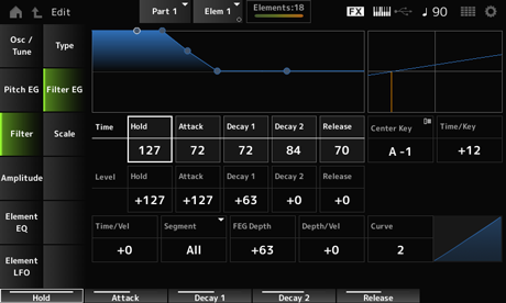
Sets the length of time it takes for maintaining the Cutoff Frequency at Hold Level starting from the moment you press a key on the keyboard. Settings: 0–127
Sets the length of time it takes for the Cutoff Frequency to change from the end of Hold Time to the Attack Level. Settings: 0–127
Sets the length of time it takes for the Cutoff Frequency to change from the Attack Level to the Decay 1 Level. Settings: 0–127
Sets the length of time it takes for the Cutoff Frequency to change from the Decay 1 Level to the Decay 2 Level. Settings: 0–127
Sets the length of time it takes for the Cutoff Frequency to change from the moment you release your finger from the key until it reaches the Release Level. Settings: 0–127
Sets the Cutoff Frequency at the moment you press the key. Settings: −128–+127
Sets the Cutoff Frequency value to change after you press the key. Settings: −128–+127
Sets the next Cutoff Frequency value to change from the Attack Level. Settings: −128–+127
Sets the Cutoff Frequency that is maintained while the key is held down. Settings: −128–+127
Sets the next Cutoff Frequency value after you release your finger from the key. Settings: −128–+127
Sets the reference note (or a key to press) for Time/Key.
With the note (key) set here, the change speed of the cutoff frequency set in Filter EG is used as is.
Sets how the speed of the frequency change in FEG responds to the position of the key.
The change speed in FEG is used for the specified key in Center Key. Settings: −64–+63
Positive values: The lower the key played, the slower the FEG change becomes; the higher the key played, the faster the FEG change becomes.
Negative values: The lower the key played, the faster the FEG change becomes; the higher the key played, the slower the FEG change becomes.
0: No changes to the FEG regardless of the key position.
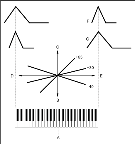
A: Center Key
B: Slow
C: Fast
D: Low key
E: High key
F: Positive value
G: Negative value
Settings: C−2–G8
Segment (FEG Time Velocity Sensitivity Segment)
Sets how the Cutoff Frequency responds to Velocity or the strength of the keystroke.
First, set the time value in Segment, and then the velocity sensitivity value in Time/Vel. Settings: Time/Vel: −64–+63
Positive value: The faster the velocity, the faster the FEG changes.
Negative value: The faster the velocity, the slower the FEG changes, while slow velocity makes the FEG change faster.
0: No changes regardless of the velocity setting.
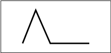
Fast velocity
(fast changes in Cutoff Frequency)
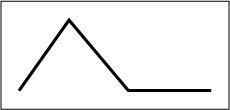
Slow velocity
(slow changes in Cutoff Frequency)
Settings: Segment: Attack, Atk+Dcy, Decay, Atk+Rls, All
Attack: Time/Vel value affects the Attack Time.
Atk+Dcy: The Time/Vel value affects the Attack Time and Decay 1 Time.
Decay: The Time/Vel value affects the Decay Time.
Atk+Rls: The Time/Vel value affects the Attack Time and Release Time.
All: The Time/Vel value affects the time-related settings in FEG.
Sets the depth range for the Cutoff Frequency change controlled by the FEG. Settings: −64–+63
0: No changes for the Cutoff Frequency by the Filter EG.
The depth range of the Cutoff Frequency change becomes wider when the setting is far from the value 0.
For negative values, Cutoff Frequency changes are reversed.
Curve (FEG Depth Velocity Sensitivity Curve)
Sets how the depth range of the Cutoff Frequency change controlled by the FEG responds to Velocity (strength of the keystroke).
Also, with the Curve setting, you can set how the FEG Depth responds to the velocity.
The vertical axis represents the velocity while the horizontal axis represents the depth range of the Cutoff Frequency change. Settings: Depth/Vel: −64–+63
Positive values: Fast velocity widens the depth range of the Filter EG changes, while slow velocity narrows the depth range.
Negative values: Fast velocity narrows the depth range of the Filter EG changes, while slow velocity widens the depth range.
0: Cutoff Frequency does not respond to Velocity.
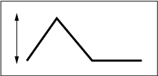
Fast velocity
(the depth range in Cutoff Frequency change is wider)
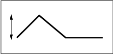
Slow velocity
(the depth range in Cutoff Frequency change is narrower)
Settings: Curve: 0–4

On the Scale screen, you can set the filter scale for the Element.
The Filter Scale function allows you to change the Cutoff Frequency of the filter depending on the pitch.
- [PERFORMANCE] → [EDIT/
] → Part selection → Element selection → Filter → Scale
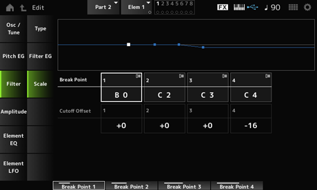
Sets the note numbers of four points to be set to Cutoff Offset. Settings: C−2–G8
The note numbers for Break Points 1 to 4 will be automatically arranged in ascending order.
Sets the value that increases or decreases the Cutoff on all four Break Points. Settings: −128–+127
When the offset value is set above or below the Cutoff value, the Cutoff Frequency never goes beyond the settings.
For any notes below Break Point 1, the value will be set to the Cutoff Frequency of Break Point 1. For any notes above Break Point 4, the value will be set to the Cutoff Frequency of Break Point 4.
On the Level/Pan screen, you can set Level and Pan (position in the stereo field) for each Element.
- [PERFORMANCE] → [EDIT/
] → Part selection → Element selection → Amplitude → Level/Pan
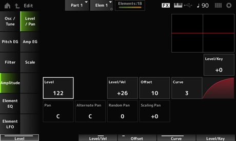
Sets how the volume of each Element responds to key position. The reference point is the volume specified in Center Key. Settings: −64–+0–+63
Positive values: The lower the key played, the softer the volume becomes; the higher the played, the louder the volume becomes.
Negative values: The lower the key played, the louder the volume becomes; the higher the key played, the softer the volume becomes.
Sets the output level (volume) for each Element. Settings: 0–127
Offset (Level Velocity Offset)
Curve (Level Sensitivity Key Curve)
Sets how the Level (Volume) responds to Velocity or the strength of the keystroke. Offset adjusts all settings specified in Level/Vel. When the value exceeds 127, the velocity is set to 127. Also, with the Curve setting, you can set how the volume responds to the velocity. The vertical axis represents the velocity while the horizontal axis represents the range for the volume changes. Settings: Level/Vel: −64–+63
Positive value: The faster the Velocity, the louder the volume becomes.
Negative value: The slower the Velocity, the louder the volume becomes.
0: No changes regardless of the Velocity setting.
Settings: Offset: 0–127
Offset (Level Velocity Offset) = 0
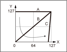
Offset (Level Velocity Offset) = 64
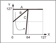
Offset (Level Velocity Offset) = 96
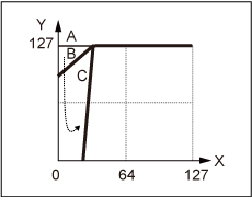
A: Level/Vel (Level Velocity Sensitivity) = 0
B: Level/Vel (Level Velocity Sensitivity) = 32
C: Level/Vel (Level Velocity Sensitivity) = 64
X: Velocity of the moment the key is pressed
Y: Velocity value sent to the internal tone generator
Settings: Curve: 0–4

Sets the Pan position (in the stereo field) for the Element.
When there are right and left Pan settings for the Elements within a Part, it may be difficult to hear the result of the pan setting. Settings: L63–C–R63
Sets the amount by which the sound is panned alternately left and right for each key you press.
The value set in Pan is the center position for the right and left movement of the Pan. Settings: L64–C–R63
Sets the amount by which the sound is panned randomly left and right for each key you press.
The value set in Pan is the center position in the stereo field. Settings: 0–127
Sets how the position of the key you press affects the position of the Pan setting.
The value set in Pan is the position for C3. Settings: −64–+0–+63
Positive values: Pan position is scaled to the left for lower keys and to the right for higher keys.
Negative values: Pan position is scaled to the right for lower keys and to the left for higher keys.
On the Amp EG screen, you can set the AEG (Amplitude Envelope Generator) Time for the Element. This lets you determine how the volume changes from the moment you press a key on the keyboard to when the sound decays.
- [PERFORMANCE] → [EDIT/
] → Part selection → Element selection → Amplitude → Amp EG
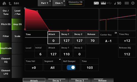
Sets the length of time it takes for the volume to change from the moment you press a key on the keyboard until when it reaches the Attack Level value. Settings: 0–127
Sets the length of time it takes for the volume to change from the Attack Level to the Decay 1 Level. Settings: 0–127
Sets the length of time it takes for the volume to change from the Decay 1 Level to the Decay 2 Level. Settings: 0–127
Sets the length of time it takes for the sound to decay after you have released the key. Settings: 0–127
Sets the volume for the moment you press the key. Settings: 0–127
Sets the volume for changing after you have pressed a key. Settings: 0–127
Sets the next volume value to change from the Attack Level. Settings: 0–127
Sets the volume that is maintained while the key is held down. Settings: 0–127
Sets the reference note (or a key to press) for Time/Key. According to the note (key) set here, the resulting sound of the pitch change set in PEG is played. Settings: C−2–G8
Sets how the speed of the volume changes in AEG responds to key position. The speed change in AEG is used for the specified key in Center Note. Settings: −64–+63
Positive values: The lower the key played, the slower the AEG volume changes; the higher the key played, the faster the AEG volume changes.
Negative values: The lower the key played, the faster the AEG volume changes; the higher the key played, the slower the AEG volume changes.
0: No AEG volume changes regardless of the key position.
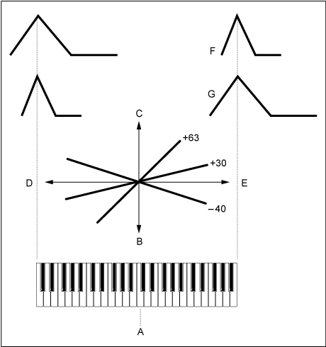
A: Center Note
B: Slow
C: Fast
D: Low keys
E: High keys
F: Positive values
G: Negative values
Adjusts the sensitivity of the AEG Time Key Follow Sensitivity to AEG Release.
The lower the value, the lesser the sensitivity. Settings: 0–127
127: AEG Time Key Follow Sensitivity is the same as Decay 1 and Decay 2.
0: AEG Time Key Follow Sensitivity does not affect the AEG Release.
Segment (AEG Time Velocity Segment)
Sets how the time for volume changes in AEG responds to Velocity or the strength of the keystroke.
First, set the time value in Segment, and then the velocity sensitivity value in Time/Vel. Settings: Time/Vel: −64–+63
Positive value: The faster the velocity, the faster the AEG volume changes.
Negative value: The faster the velocity, the slower the AEG volume changes; the slower the velocity, the faster the AEG volume changes.
0: No changes regardless of the velocity setting.
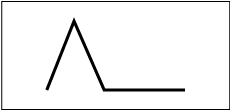
Fast velocity (fast volume change)
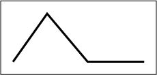
Slow velocity (slow volume change)
Settings: Segment: Attack, Atk+Dcy, Decay, Atk+Rls, All
Attack: Time/Vel value affects the Attack Time.
Atk+Dcy: The Time/Vel value affects the Attack Time and Decay 1 Time.
Decay: The Time/Vel value affects the Decay Time.
Atk+Rls: The Time/Vel value affects the Attack Time and Release Time.
All: The Time/Vel value affects the time-related settings in AEG.
By setting this switch On, you can connect a separately sold foot controller FC3A to the [SUSTAIN] jack on the rear panel and use the half-damper function for your keyboard performance.
The Half-damper function gives you greater expressive control over sound decay, letting you use damper pedal operation just as you would on an acoustic piano—continuously and not just as an on/off switch. Settings: Off, On
Sets the time from the moment you have released a key while you are pressing the foot controller FC3A fully down to when the sound decays when the Half Damper (Half Damper Switch) is set to On. This parameter is not shown when Half Damper (Half Damper Switch) is set to Off.
You can adjust the decay time from the Half Damper Time to the Release Time by changing the amount you press on the pedal.
When you release the pedal, the Release Time is used for decaying sound. By setting the Release Time to a small value, and Half Damper Time to a large value, you can play a natural decaying sound, like on an acoustic piano.Settings: 0–127
On the Scale screen, you can set the Amplitude Scale for the Element.
This changes the volume according to the key position on the keyboard.
- [PERFORMANCE] → [EDIT/
] → Part selection → Element selection → Amplitude → Scale
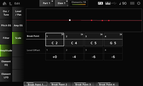
Sets the note number for Level Offset. Settings: C−2–G8
The note numbers for Break Points 1 to 4 will be automatically arranged in ascending order.
Sets the values of four Break Points for controlling Level. Settings: −128–+127
On the Element EQ screen, you can set the equalizer for the Element.
- [PERFORMANCE] → [EDIT/
] → Part selection → Element selection → Element EQ
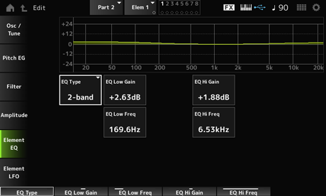
Selects the desired EQ type. Settings: 2-band, P.EQ, Boost6, Boost12, Boost18, Thru
2-band: Shelving EQ that boosts or cuts the band of signals above or below a certain frequency (Low Freq or High Freq).
P.EQ: Parametric EQ that boosts or cuts the signal level (Gain) around the Center Frequency (Freq).
Boost6: Boosts the level by 6 dB.
Boost12: Boosts the level by 12 dB.
Boost18: Boosts the level by 18 dB.
Thru: Bypasses the equalizer leaving the entire signal unaffected.
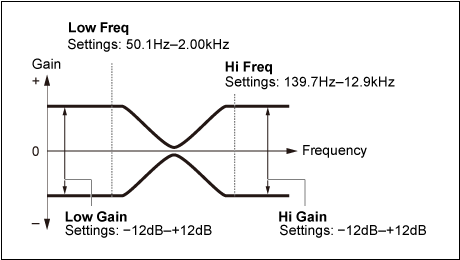
Sets the signal level of the Low band. Settings: −12.00dB–+12.00dB
Sets the frequency of the Low band. Settings: 50.1Hz–2.00kHz
Sets the signal level of the High band. Settings: −12.00dB–+12.00dB
Sets the frequency of the High band. Settings: 503.8Hz–10.1kHz
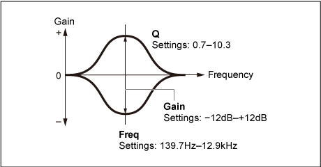
Sets the signal level for the frequency range set in EQ Freq. Settings: −12.00dB–+12.00dB
Sets the frequency to be cut or boosted. Settings: 139.7Hz–12.9kHz
By boosting or cutting the signal level of the frequency set in EQ Freq, you can create various frequency response curves. Settings: 0.7–10.3
On the Element LFO screen, you can set the LFO (Low Frequency Oscillator) for the Element. The LFO (Low Frequency Oscillator) for the Element generates signals in the low band, and you can use it for modulation (cyclical variation) of the pitch, filter, and amplitude.
- [PERFORMANCE] → [EDIT/
] → Part selection → Element selection → Element LFO
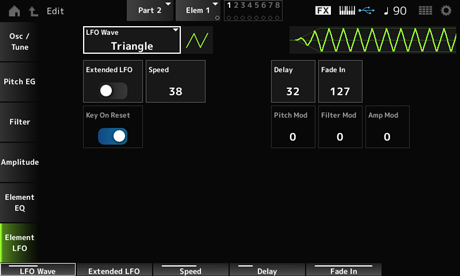
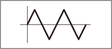
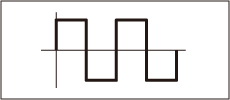
Selects an LFO wave, for creating various distinct types of modulation. Settings: Saw, Triangle, Square
Saw (Sawtooth wave)
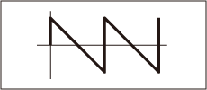
Triangle (Triangle wave)
Square (Square wave)
Switches between the old set of settings (Off: 0–63) and a new set of settings with higher resolution (On: 0–415) for Speed (LFO Speed).
To maintain compatibility of data created with the old settings, set this parameter to Off. Settings: Off, On
Sets the speed of LFO Wave changes. The larger the value of this parameter, the faster the speed becomes. Settings: 0–63 (ExtendedLFO set to Off), 0–415 (ExtendedLFO is set to On)
Sets the delay time between the moment you press a key on the keyboard and the moment the LFO comes into effect. Settings: 0–127
Sets the time length for the LFO effect to fade in after you have released the key and the delay time set in Delay has elapsed. Settings: 0–127
The larger the value, the longer it takes for the LFO effect to reach the maximum.
0: LFO changes to the maximum value without any fade-ins.
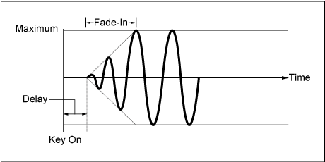
Low value: Fast fade-in
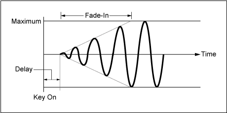
High value: Slow fade-in
Resets the oscillation of the LFO when a key is pressed. Settings: Off, On

This parameter creates a vibrato effect (cyclical changes to the pitch) by using LFO waves.
Setting the parameter to larger values results in greater change to the volume. Settings: 0–127
This parameter creates a wah effect (cyclical changes to the filter cutoff frequency) by using LFO waves.
Larger values result in greater range for cutoff frequency changes. Settings: 0–127
This parameter creates a tremolo effect (cyclical changes in the volume) by using LFO waves.
Setting the parameter to larger values results in greater change to the volume. Settings: 0–127