The screen here is the same as the one opened from General/Pitch → Part Settings on the Part Edit (AWM2).
The screen here is the same as the one opened from General/Pitch → Zone Settings on the Part Edit (AWM2).
On the AN-X Settings screen, you can set the parameters that are specific to the AN-X sound engine.
- [PERFORMANCE] → Part Common selection → [EDIT/
] → General/Pitch → AN-X Settings
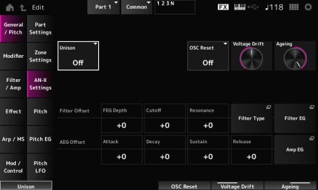
Creates thickness by layering multiple sounds. Settings: Off, 2, 4
Sets how the pitch of the layered sound is to be shifted. Settings: 0–15
Sets how the layered sounds are spread in the stereo field. Settings: 0–15
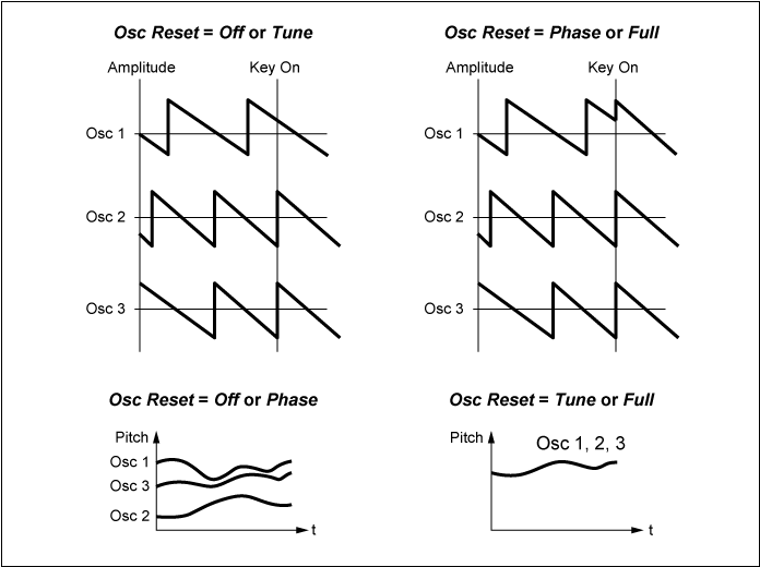
Specifies how to reset the Oscillator. Settings: Off, Phase, Tune, Full
Off: Does not reset.
Phase: Resets the phase of OSC 1–3 at key-on.
Tune: Makes the pitch of OSC 1–3 uniform.
Full: Enables both Phase and Tune simultaneously.
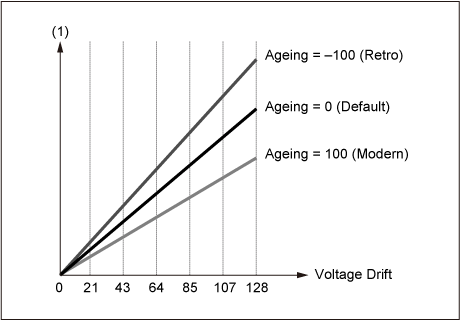
Specifies the pitch of the Oscillator and variation of Filter Cutoff.
Oscillator pitch and variation of Filter Cutoff are affected by Ageing. Settings: 0–127
0: No variation
64: Standard
127: Maximum variation
Adjusts the frequency response as well as OSC Pitch, Filter Cutoff, and EG Time according to the virtual age of the instrument model. Settings: −100 (old)–+100 (new)
The screen here is the same as the one opened from General/Pitch → Pitch on the Part Edit (AWM2), except that Legato Slope (Portamento Legato Slope) is invalid.
On the Pitch EG screen, you can set the Pitch Envelope Generator.
You can use it to set how the sound changes over time, starting from the moment you press a key on the keyboard to when the sound decays.
- [PERFORMANCE] → Part Common selection → [EDIT/
] → General/Pitch → Pitch EG
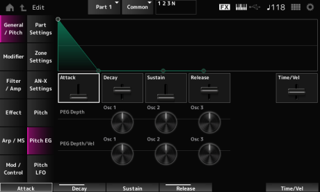
Sets the length of time it takes for the EG to reach the maximum. Settings: 0–255
Sets the length of time it takes for the EG to reach the Sustain value. Settings: 0–255
Sets the sustain level. Settings: 0–511
Sets the length of time it takes after you have released the key until the EG reaches the value 0. Settings: 0–255
Sets how the velocity changes the EG over time.
The larger the value, the faster the EG changes over time when the keys are played with fast velocity. Settings: −255–0–+255
Sets the maximum amount of pitch change for the EG (in cents). Settings: −4800–+4800 cents
0: No pitch change
The further the depth is from the value 0, the wider the pitch change range becomes.
Negative value: Pitch change is inverted.
Sets how the depth range of the pitch change controlled by the PEG responds to Velocity or the strength of the keystroke.
Also, with the Curve setting, you can set how the PEG Depth responds to velocity. The vertical axis represents velocity while the horizontal axis represents the depth range of the pitch change. Settings: −255–+255
Positive value: Faster velocity values widen the depth range of the PEG, while slower values narrow the depth range.
Negative value: Faster velocity values narrow the depth range of the PEG, while slower values widen the depth range.
0: No PEG changes regardless of the velocity setting.
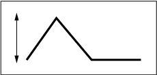
Fast velocity
(the depth range in pitch change is wider)
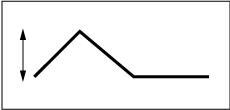
Slow velocity
(the depth range in pitch change is narrower)
On the Pitch LFO screen, you can set the Pitch LFO.
- [PERFORMANCE] → Part Common selection → [EDIT/
] → General/Pitch → Pitch LFO
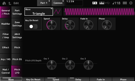
Selects the LFO Wave and sets the type of cyclical changes to the LFOs. Settings: Saw, Square, Triangle, Sine, Random

Resets the phase of the LFO when a key is pressed. Settings: Off, On

Sets the speed of LFO wave changes. Settings: 0–415
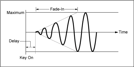
Sets the delay time between the moment you press a key on the keyboard and the moment the LFO comes into effect. Settings: 0–127
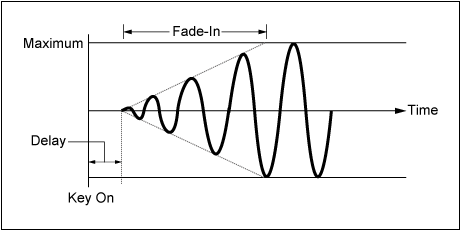
Sets the time length for the LFO effect to fade in after you have released the key and the delay time set in Delay has elapsed. Settings: 0–214
The larger the value, the longer it takes for the LFO effect to reach the maximum.
0: The LFO changes to the maximum value without any fade-ins.
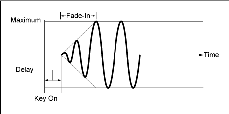
Small value: fast fade-in
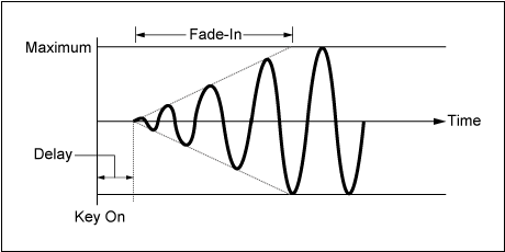
Large value: slow fade-in
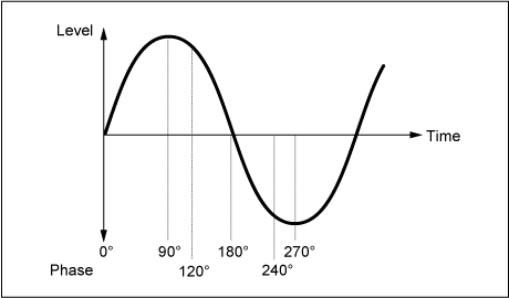
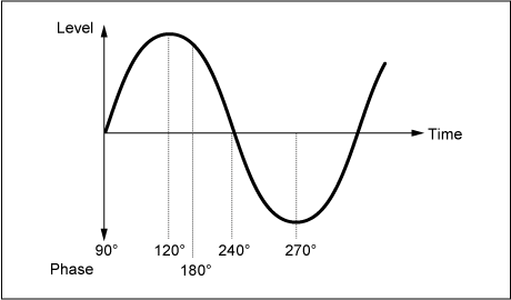
Sets the phase for resetting the wave when a key is pressed. Settings: 0, 30, 45, 60, 90, 120, 135, 150, 180, 210, 225, 240, 270, 300, 315, 330 (°)
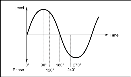
Phase of the wave
Sets the depth range of pitch change controlled by the LFO. Settings: −4800–+4800 cents
0: No pitch change
The further the depth is from the value 0, the wider the pitch change range becomes.
Negative value: Pitch change is inverted.
Modifier is a function block for adding distortion to the signal output from the OSC block and for adding harmonics to the sound.
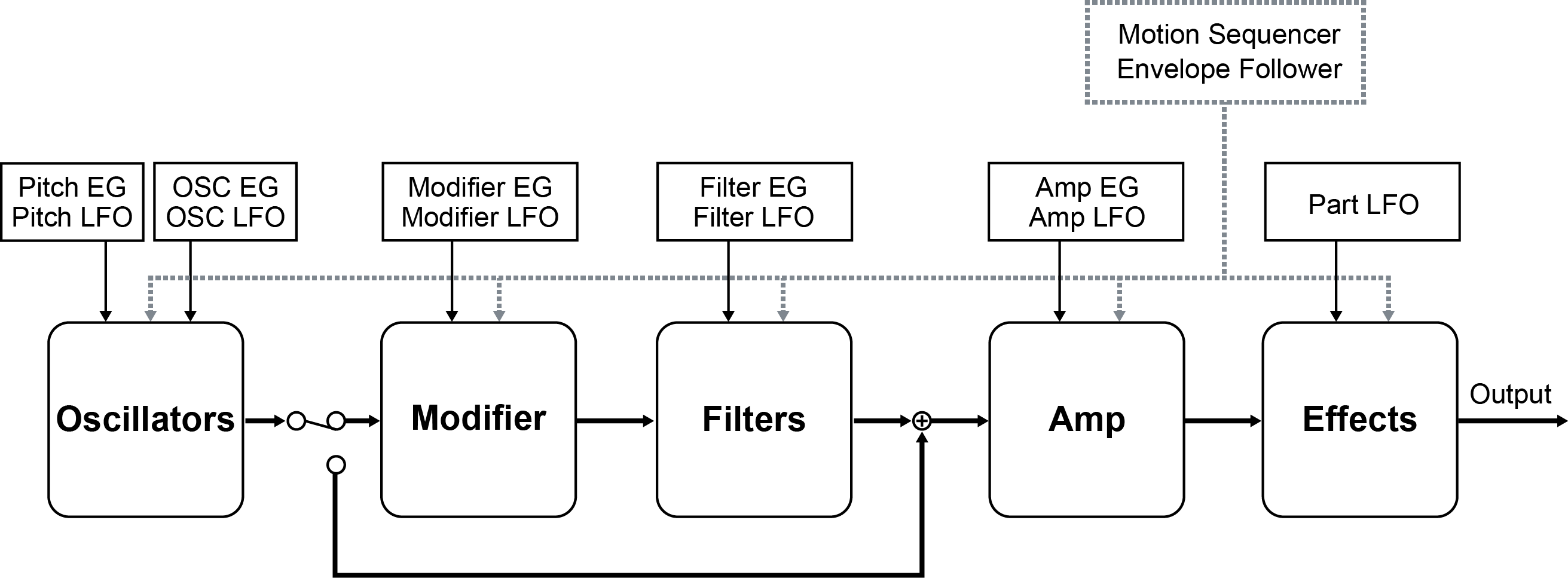
Wave folder is an effect created by folding waveforms according to the specified value. This effect lets you create smooth changes from delicate distortion to sonic destruction. With the AN-X sound engine, you can use this effect on each note independently.
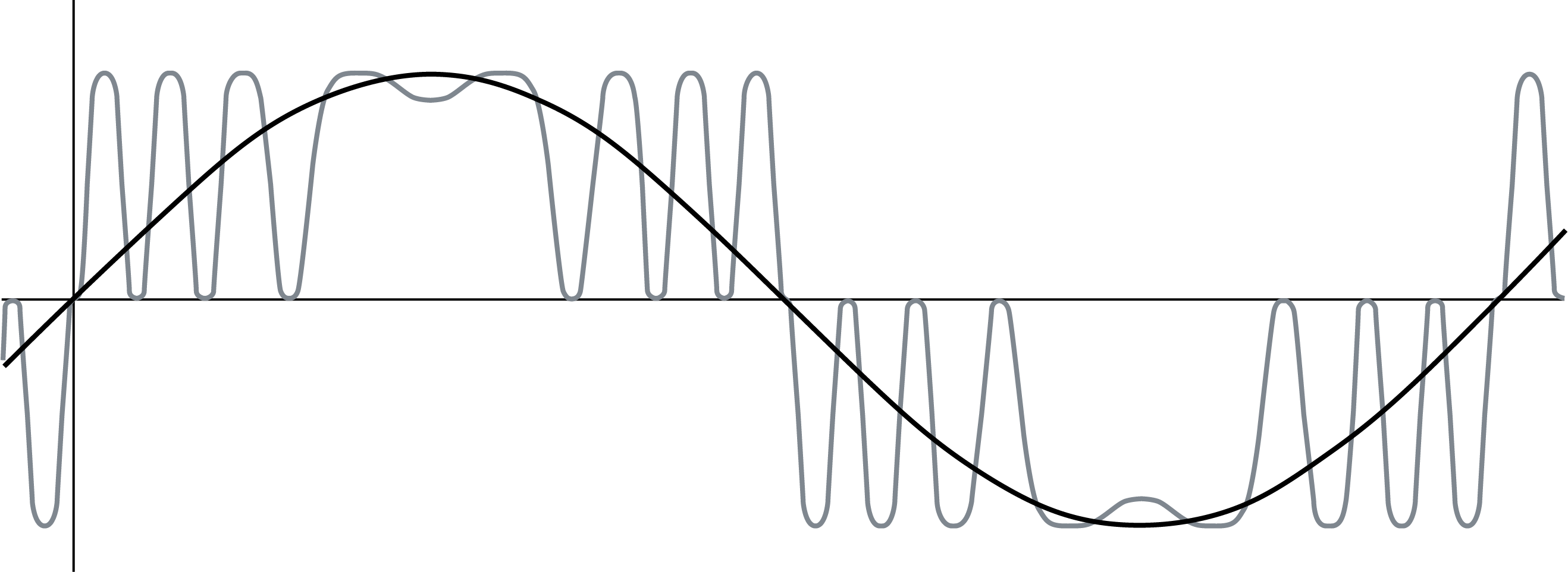
Various controllers including EG, LFO, Velocity, and Polyphonic Aftertouch are available for controlling this effect in real-time.
- [PERFORMANCE] → Part Common selection → [EDIT/
] → Modifier → Wave Folder
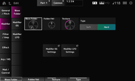
Specifies the degree of wave folding.Settings: 0–255
Sets how the Wave Folder responds to Velocity.Settings: −255–0–+255 Changes the texture of the Wave Folder.Settings: 0–255 Changes the Wave Folder type.Settings: Soft, Hard Opens the Modifier → Modifier EG screen. Opens the Modifier → Modifier LFO screen. On the Modifier EG screen, you can set the Envelope Generator for the Modifier. Sets the length of time it takes for the EG to change from the moment you press a key on the keyboard until it reaches the maximum.Settings: 0–255 Sets the length of time it takes for the EG to change from the moment you press a key on the keyboard until it reaches the value set at the Sustain level.Settings: 0–255 Sets the sustain level.Settings: 0–511 Sets the length of time for the EG to reach a value of 0 after you have released the key.Settings: 0–255 Sets how the velocity changes the EG over time. Sets how the Wave Folder responds to Modifier EG.Settings: −127–+127 On the Modifier LFO screen, you can set the Modifier LFO. Selects the LFO Wave and sets the type of cyclical changes to the LFOs.Settings: Saw, Square, Triangle, Sine, Random Resets the phase of the LFO when a key is pressed.Settings: Off, On Sets the speed of LFO wave changes.Settings: 0–415 Sets the delay time between the moment you press a key on the keyboard and the moment the LFO comes into effect.Settings: 0–127 Sets the time length for the LFO effect to fade in after you have released the key and the delay time set in Delay has elapsed.Settings: 0–214 Small value: fast fade-in Large value: slow fade-in Sets the phase for resetting the wave when a key is pressed.Settings: 0, 30, 45, 60, 90, 120, 135, 150, 180, 210, 225, 240, 270, 300, 315, 330 (°) Phase of the wave Sets the depth range of pitch change controlled by the LFO.Settings: −127–+127 On the Mixing screen, you can set the output of each Oscillator while checking the signal flow diagram for the AN-X part. Sets how OSC3 modulates OSC1 and OSC2 by using frequency modulation (FM). Settings: 0–255 Opens the OSC/Tune screen for Oscillator Edit. Opens the Noise screen. Sets how the OSC3 modulates OSC1 and OSC2 by using Ring Modulation. Settings: 0–255 1, 2, and 3 are for setting the Oscillator volume. Sets the output destination for the Oscillators and Noise. Settings: Filter, Amp Opens the Filter/Amp → Filter Type screen for Part Edit (AN-X). Opens the Filter/Amp → Amp EG screen for Part Edit (AN-X). On the Filter Type screen, you can select the filter type. Sets the filter. Cuts the signals above the value set in Cutoff Frequency. LPF24: −24 dB/oct A Filter Type that only passes signals above the Cutoff Frequency. HPF24: −24 dB/oct A Filter Type that only passes signals for a specific frequency band (Cutoff Frequency) and cuts all other signals. BPF12: −12 dB/oct Sets the cutoff frequency. The frequency set here is used by the filter set in Type. Settings: 0–1023 Sets the size of the Resonance. Settings: 0–255 Sets how Cutoff Frequency responds to Velocity or the strength of the keystroke. Settings: −255–+255 Sets how the resonance level responds to Velocity or the strength of the keystroke. Sets how the cutoff frequency level of the filter responds to the key position. When the value is set to 1oct, both the pitch and the cutoff frequency change at the same rate. Settings: Off, 1/3oct, 1/2oct, 2/3oct, 1oct, 2oct Sets the amount of distortion controlled by the Saturator section of the filter. Settings: 0.0–60.0 (dB) (in units of 0.75 dB) Sets how the Drive responds to Velocity. Settings: −255–0–+255 Sets the output level for the Filter. Settings: −12.0–+12.0 (dB) (in units of 0.375 dB) On the Filter EG screen, you can set the Filter Envelope Generator. Sets the length of time it takes for the EG to reach the maximum. Settings: 0–255 Sets the length of time it takes for the EG to change from the maximum to the Sustain level. Settings: 0–255 Sets the sustain level. Settings: 0–511 Sets the length of time it takes for the EG to reach a value of 0 after you have released the key. Settings: 0–255 Sets how the Cutoff Frequency responds to Velocity or the strength of the keystroke. Settings: −255–0–+255 Sets the depth range for the cutoff frequency change controlled by the FEG. Settings: −9600–+9600 cents (in units of 50 cents) Sets how the depth range of the cutoff frequency change controlled by the FEG responds to Velocity or the strength of the keystroke. Settings: −255–0–+255 On the Filter LFO screen, you can set the Filter LFO. Selects an LFO wave. By using the wave you have selected here, you can create various types of modulation. Settings: Saw, Square, Triangle, Sine, Random Resets the oscillation of the LFO when a key is pressed. Sets the speed of LFO wave changes. Settings: 0–415 Sets the delay time between the moment you press a key on the keyboard and the moment the LFO comes into effect. Sets the time length for the LFO effect to fade in after you have released the key and the delay time set in Delay has elapsed. Settings: 0–214 Small value: fast fade-in Large value: slow fade-in You can set the initial phase for the time the LFO Wave is reset. Settings: 0, 30, 45, 60, 90, 120, 135, 150, 180, 210, 225, 240, 270, 300, 315, 330 (°) Phase of the wave Sets the depth of the LFO Wave control for Filter 1 and Filter 2. Settings: −9600–+9600 (cents) (in units of 50 cents) On the Amp EG screen, you can set the AEG (Amplitude Envelope Generator). Sets the length of time it takes from the moment you press a key on the keyboard to when the Amplitude Level is reached. Settings: 0–255 Sets the length of time it takes for the volume to change from the Amplitude Level to the Sustain Level. Settings: 0–255 Sets the volume that is maintained while the key is held down. Settings: 0–511 Sets the length of time it takes after you have release the key to when the sound decays. Settings: 0–255 Sets the length of time it takes for volume changes in AEG to respond to Velocity or the strength of the keystroke. Settings: −255–+255 Fast velocity (fast volume change) Slow velocity (slow volume change) Sets the volume level of Amplitude. Settings: 0–511 Sets how the Amplitude level responds to Velocity. Settings: −255–0–+255 Sets how the Amp Level responds to pitch. Sets the amount of distortion controlled by the Saturator of the Amplitude section. Settings: 0.0–60.0 (dB) (in units of 0.75 dB) On the Amp LFO screen, you can set the Amplitude LFO. Selects an LFO wave. By using the wave you have selected here, you can create various types of modulation. Settings: Saw, Square, Triangle, Sine, Random Resets the oscillation of the LFO when a key is pressed. Settings: Off, On Sets the speed of LFO wave changes. Settings: 0–415 Sets the delay time between the moment you press a key on the keyboard and the moment the LFO comes into effect. Sets the time length for the LFO effect to fade in after you have released the key and the delay time set in Delay has elapsed. Settings: 0–214 Small value: fast fade-in Large value: slow fade-in You can set the initial phase for the time the LFO wave is reset. Settings: 0, 30, 45, 60, 90, 120, 135, 150, 180, 210, 225, 240, 270, 300, 315, 330 (°) Phase of the wave Sets the depth range of volume changes controlled by the LFO. Settings: −127–+127 The screen here is almost the same as the one opened from Effect → Routing on Part Edit (AWM2), with the exceptions listed below. The screen here is the same as the one opened from Effect → InsA or InsB on Part Edit (AWM2). The screen here is the same as the one opened from Effect → 3-band EQ on Part Edit (AWM2). The screen here is the same as the one opened from Effect → 2-band EQ on Part Edit (AWM2). The screen here is the same as the one opened from Arpeggio → Common on Part Edit (AWM2). The screen here is the same as the one opened from Arpeggio → Individual on Part Edit (AWM2). The screen here is the same as the one opened from Arpeggio → Advanced on Part Edit (AWM2). The screen here is the same as the one opened from Motion Seq → Common on Part Edit (AWM2). The screen here is the same as the one opened from Motion Seq → Lane on Part Edit (AWM2). The screen here is the same as the one opened from Mod/Control → Control Assign on Part Edit (AWM2), except that the available Destination settings are different. Use the parameters shown below, instead of Element Sw and others. You can set the controller setting for each Oscillator on or off. This parameter is shown only when the selected Destination is related to Oscillators. You can set the controller setting for each Filter on or off. The screen here is the same as the one opened from Mod/Control → After Touch on Part Edit (AWM2), except that the available Destination settings are different. The screen here is the same as the one opened from Mod/Control → Tx/Rx Switch on Part Edit (AWM2). The screen here is the same as the one opened from Mod/Control → Control Settings on Part Edit (AWM2). The screen here is the same as the one opened from Mod/Control → Part LFO on Part Edit (AWM2). Adjusts the Depth for each Oscillator or Filter.
] → Modifier → Modifier EG
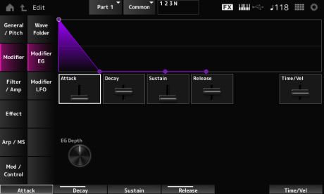
Larger the value the faster the changes of EG over time when the keys are played with fast velocity.
Settings: −255–0–+255
] → Modifier → Modifier LFO
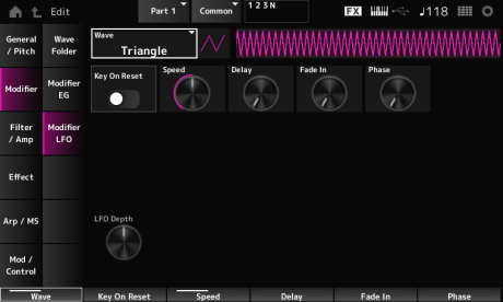


The larger the value, the longer it takes for the LFO effect to reach the maximum.
0: The LFO changes to the maximum value without any fade-ins.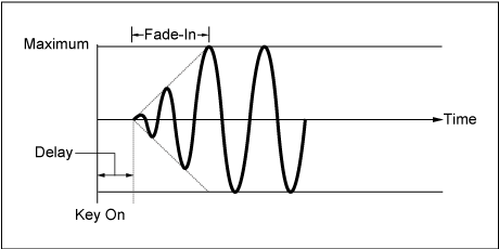
0: No pitch change
The further the depth is from the value 0, the wider the pitch change range becomes.
Negative value: Pitch change is inverted.
] → Filter / Amp → Mixing
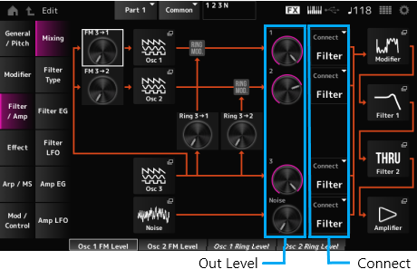
FM 3 → 2 (Oscillator 2 FM Level)
Osc 2 (Oscillator 2)
Osc 3 (Oscillator 3)
Useful for creating various SFX sounds by using filters such as VCF and HPF on the noise signals.
Ring 3 → 2 (Oscillator 2 Ring Level)
2 (Oscillator 2 Out Level)
3 (Oscillator 3 Out Level)
Noise (Noise Out Level)
Noise is for adjusting the level of the signal output from the Noise Unit. You can control the level balance with other signals such as OSC 1, OSC 2, and Ring Modulator. Settings: 0–511
Connect 2 (Oscillator 2 Out Select)
Connect 3 (Oscillator 3 Out Select)
Noise Connect (Noise Out Select)
Filter 2
The available parameters differ depending on the filter type you have selected here.
] → Filter / Amp → Filter Type
Filter 2 Type
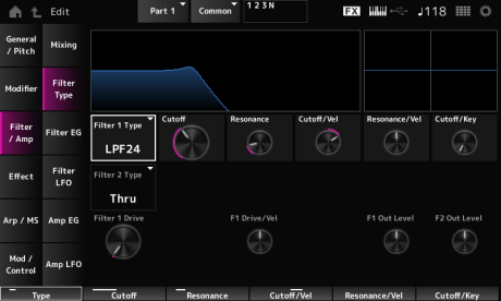
The filters available for the AN-X are grouped into three types: LPF, HPF, and BPF. Settings: Thru, LPF24, LPF18, LPF12, LPF6, HPF24, HPF18, HPF12, HPF6, BPF12, BPF6
The sound becomes brighter as you raise the Cutoff Frequency, since more signals are passed by the filter.
The sound becomes darker as you lower the Cutoff Frequency, since signals are cut or blocked by the filter.
You can produce a distinctive “peaky” sound by raising the Resonance or boosting the signal level near the Cutoff Frequency.
This Filter Type is very popular and useful for producing classic synthesizer sounds.
LPF18: −18 dB/oct
LPF12: −12 dB/oct
LPF6: −6 dB/oct
You can produce a distinctive “peaky” sound by raising the Resonance or boosting the signal level near the Cutoff Frequency.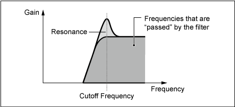
HPF18: −18 dB/oct
HPF12: −12 dB/oct
HPF6: −6 dB/oct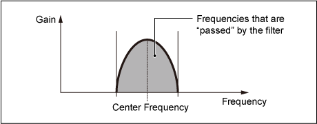
BPF6: −6 dB/oct
Positive value: The faster the Velocity, the higher the Cutoff Frequency value.
Negative value: The slower the Velocity, the higher the Cutoff Frequency value.
0: Cutoff Frequency does not respond to Velocity.
This parameter may not be available depending on the Filter Type. Settings: −255–+255
Positive value: The higher the Velocity, the greater the Resonance becomes.
Negative value: The lower the Velocity, the greater the Resonance becomes.
0: Resonance value does not change in response to Velocity.
Filter 2 Drive (Filter 2 Saturator Drive)
Filter 2 Drive/Vel (Filter 2 Saturator Drive Velocity Sensitivity)
F2 Out Level (Filter 2 Out Level)
You can set how the Filter Cutoff changes over time, starting from the moment you press a key on the keyboard to when the sound decays.
] → Filter / Amp → Filter EG
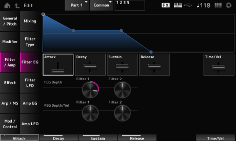
Positive values: The faster the velocity the faster the FEG changes
Negative value: Fast velocity values result in slower FEG changes, while slow velocity values result in faster FEG changes.
0: No changes regardless of the Velocity setting.
0: No changes to the cutoff frequency by the Filter EG.
The depth range of the cutoff frequency change becomes wider the further the setting is from a value of 0.
Negative values: Cutoff frequency changes are reversed.
Positive values: Faster velocity values widen the depth range of the Filter EG, while slower values narrow the depth range.
Negative values: Faster velocity values narrow the depth range of the Filter EG, while slower values widen the depth range.
0: Cutoff frequency does not respond to the Velocity.
] → Filter / Amp → Filter LFO
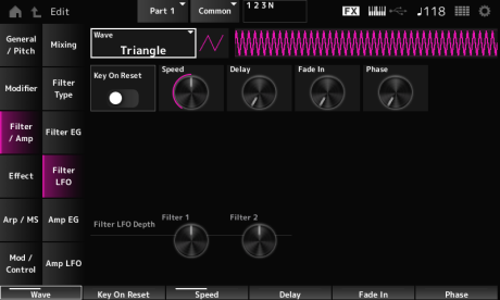

Settings: Off, On
The larger the value, the longer the delay for the LFO to come into effect. Settings: 0–127
The larger the value, the longer it takes for the LFO effect to reach the maximum.
0: The LFO changes to the maximum value without any fade-ins.


By setting the Amp EG, you can set how the volume changes from the moment you press a key on the keyboard to when the sound decays.
] → Filter / Amp → Amp EG
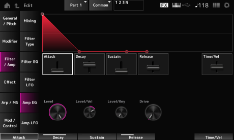
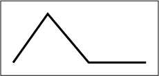
Positive value: The faster the velocity, the faster the AEG volume changes.
Negative value: Fast velocity values result in slower AEG volume changes, while slow velocity values result in faster AEG volume changes.
0: No changes regardless of the velocity setting.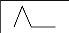
When Amplitude Level Key is set to 127, the Amp Level goes down 6 dB as the pitch goes up one octave. Settings: 0–127
] → Filter / Amp → Amp LFO
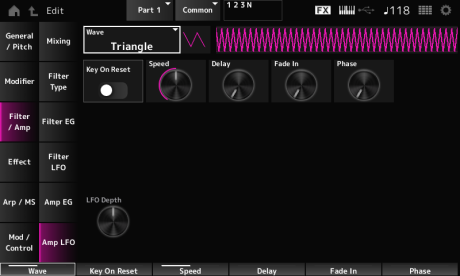


The larger the value, the longer the delay time for the LFO to come into effect. Settings: 0–127
The larger the value, the longer it takes for the LFO effect to reach the maximum.
0: The LFO changes to the maximum value without any fade-ins.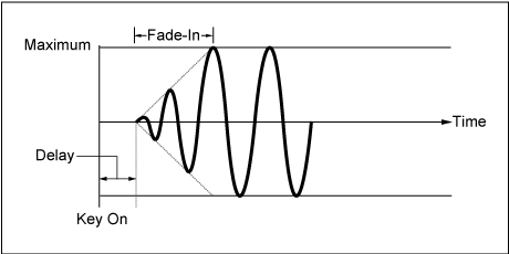
Usually, there are three switches shown, but when the Destination is set to OSC FM or OSC Ring, only two of them will be shown. Settings: Off, On
This parameter is shown only when the selected Destination is related to filters. Settings: Off, On
Also, the parameter shown below is the one available, instead of Element Depth Ratio.
Set this parameter to Off to turn off the LFO.
This parameter is shown only when the selected Destination is related to Oscillator or Filter.Settings: Off, 0–127